Radio communication system, terminal apparatus and base station apparatus

a technology of radio communication system and terminal, applied in the direction of multiplex communication, orthogonal multiplex, wireless commuication services, etc., can solve the problems of large power consumption of the terminal, inability to accurately estimate the characteristics of the transmission channel, and inability to meet the needs of large power consumption

Inactive Publication Date: 2005-10-20
KK TOSHIBA
View PDF34 Cites 253 Cited by
  • Summary
  • Abstract
  • Description
  • Claims
  • Application Information

AI Technical Summary

Problems solved by technology

When a signal is transmitted using OFDM, large power consumption is inevitably required.
Therefore, when OFDM is applied to a conventional radio communication system to realize a high-speed down channel (from a base station to a terminal), the same bandwidth and modulation method (OFDM) are used in an up channel (from the terminal to the base station), thus requiring large power consumption of the terminal.
In such radio communication system that uses asymmetric up and down radio links, since different radio frequencies are used in up and downstream communications, the characteristics of a transmission channel cannot be accurately estimated.
Therefore, techniques such as transmission power control, directivity control, adaptive modulation, and the like cannot be effectively used, thus deteriorating the radio channel quality.
However, since up and downstream communications use different radio frequencies, the characteristics of a transmission channel cannot be accurately estimated, resulting in poor communication quality of up and downstream communications.

Method used


Image

  • Radio communication system, terminal apparatus and base station apparatus
  • Radio communication system, terminal apparatus and base station apparatus
  • Radio communication system, terminal apparatus and base station apparatus

Examples


first embodiment

(First Embodiment)

[0087] The arrangements of a base station and terminal which can be applied to the radio communication system that performs two-way communications, i.e., a downstream OFDM communication and upstream FH communication, will be described first.

(Arrangement of Base Station)

[0088]FIG. 18 shows an example of the arrangement of the base station.

[0089] Data to be transmitted from the base station to respective users #1 to #N are sorted by a user assignment unit 1 using FH pattern information output from an UL FH user assignment unit 8 and user assignment information output from a DL OFDM user assignment unit 7. The sorted signals (divided into subcarriers) addressed to respective users are modulated by an OFDM transmitter unit 2, as shown in FIG. 58. That is, in the OFDM transmitter unit 2, a subcarrier modulator 2a modulates subcarrier signals, and an IFFT unit 2b generates a multi-carrier signal by IFFT (inverse Fourier transformation). A guard interval appending uni...

second embodiment

(Second Embodiment)

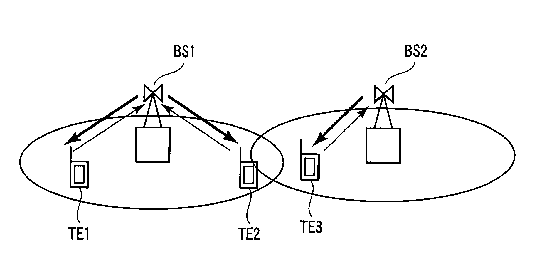
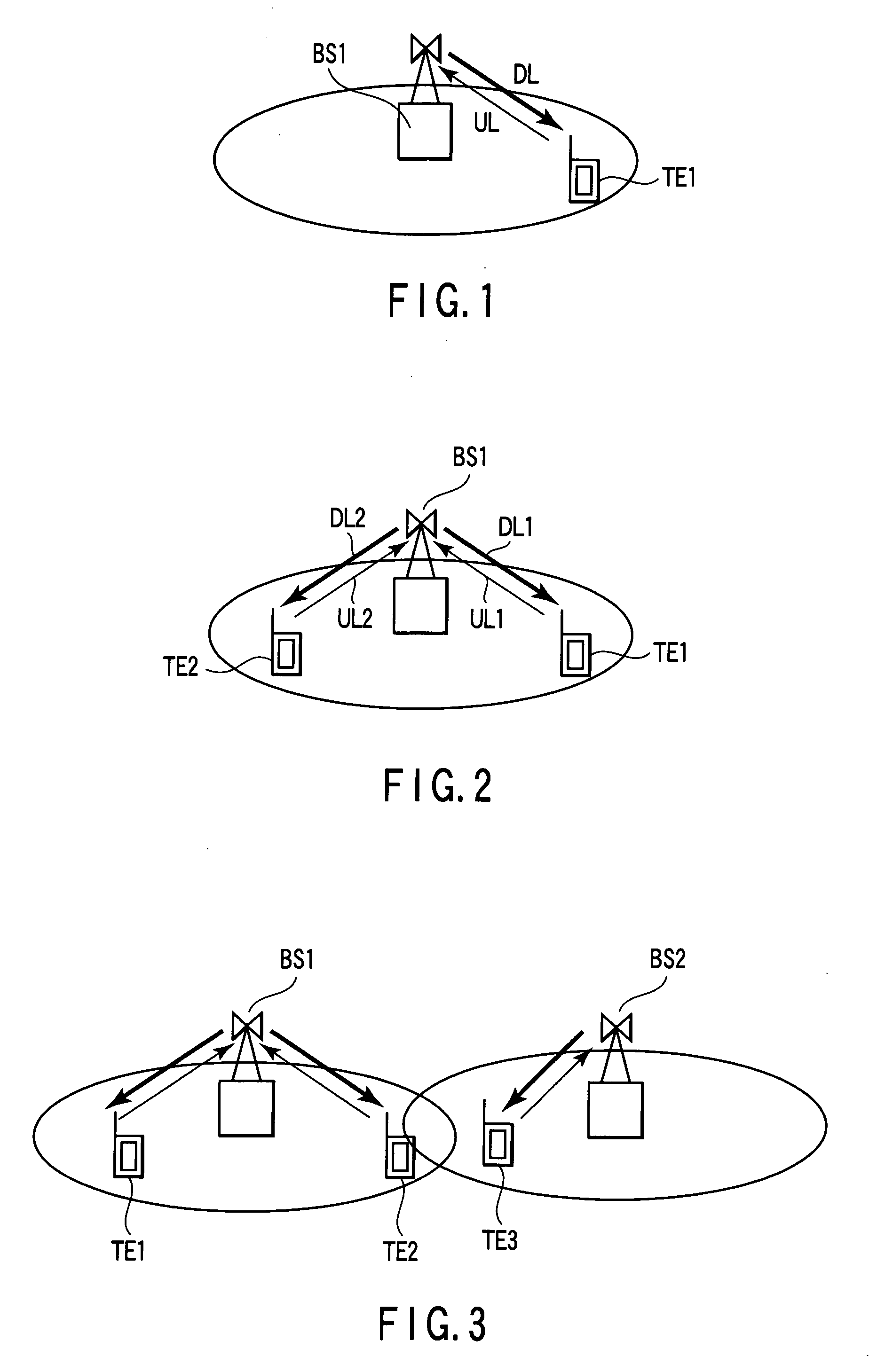
[0174] A schematic arrangement of a whole radio communication system according to the second embodiment will be described below with reference to FIG. 2. A base station BS1 transmits downstream OFDM signals DL1 and DL2 to terminals TE1 and TE2 for a predetermined period of time. Upon completion of transmission of the downstream OFDM signals by the base station, the terminals TE1 and TE2 transmit upstream FH signals UL1 and UL2 using the same frequency bands as the downstream OFDM signals to the base station BS1. In this way, the downstream OFDM signals and upstream FH signals are temporally multiplexed.

[0175] The base station BS1 transmits a time synchronization signal, paging signal (a signal that notifies each terminal of incoming call), and the like using the frequency bands other than those which are used by the downstream OFDM signals and upstream FH signals.

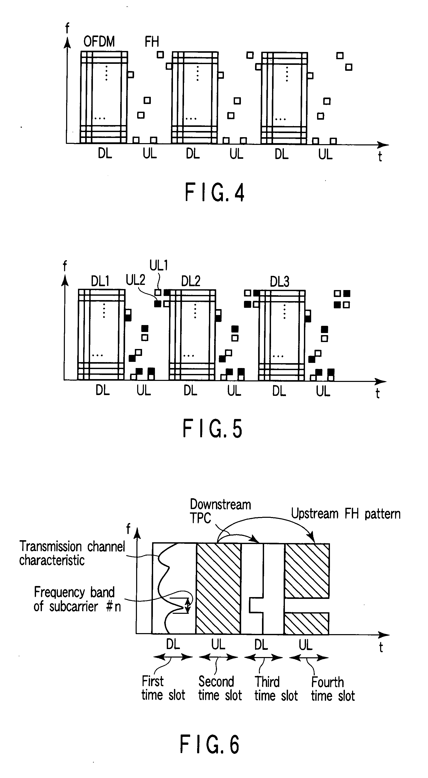
[0176]FIG. 20 shows a slot format example. The base station BS1 transmits data using OFDM to respect...

third embodiment

(Third Embodiment)

[0188] A schematic arrangement of a whole radio communication system according to the third embodiment is the same as that in the second embodiment.

[0189]FIG. 23 shows a slot format example of the radio communication system according to the third embodiment. A base station BS1 transmits data using OFDM to respective terminals using a frequency-time region 201 (subcarriers #1 to #12 and times “1” to “4”). After a guard time 202 elapses upon completion of transmission of the downstream OFDM signal by the base station BS1, each terminal transmits an FH signal using a hopping pattern which is determined in advance with the base station within the range of a frequency-time region 203 (subcarriers #1 to #12 and times “6” to “11”). Note that a hopping pattern that is distributed across all the frequencies (subcarriers #1 to #12) is preferably used in one up slot.

[0190] After a guard time 204 elapses upon completion of transmission of the upstream FH signal by each termi...


PUM


Abstract

a radio communication system which includes a base station apparatus and terminal apparatuses and performs TDD two-way communications using an OFDM signal including subcarriers in a downstream communication from the base station apparatus to each terminal apparatus, and an FH signal having the same frequency band as that of the subcarriers in an upstream communication from the each terminal apparatus to the base station apparatus, the each terminal apparatus estimates transmission channel characteristics of the subcarriers based on the OFDM signal received, transmits an estimation result of the estimation unit to the base station apparatus, and the base station apparatus assigns, to the each terminal apparatus, at least one of subcarriers to be used in the downstream communication of the subcarriers and a hopping pattern to be used in the upstream communication, based on the estimation result transmitted from the each terminal apparatus.

Description

CROSS-REFERENCE TO RELATED APPLICATIONS [0001] This application is based upon and claims the benefit of priority from prior Japanese Patent Application No. 2004-102500, filed Mar. 31, 2004, the entire contents of which are incorporated herein by reference. BACKGROUND OF THE INVENTION [0002] 1. Field of the Invention [0003] Most of conventional radio communication systems that make two-way communications between a base station and terminal use symmetric up and down radio links that use the same modulation method in upstream and downstream communications (e.g., see Jpn. Pat. Appln. KOKAI Publication No. 2000-299681). [0004] 2. Description of the Related Art [0005] As one of modulation methods that implements high-speed data transfer, OFDM is known. A signal modulated by OFDM includes a plurality of subcarriers, has a broad dynamic range as a time waveform, and requires a transmission power amplifier to have linearity. When a signal is transmitted using OFDM, large power consumption is...

Claims


Application Information

Patent Timeline
Patent Type & Authority Applications(United States)
IPC IPC(8): H04B1/707H04B1/713H04B1/7143H04J11/00H04J3/00H04J13/00H04L5/02H04L5/14H04L27/26H04W16/02H04W72/00H04W72/08
CPCH04L5/0007H04L5/0016H04L5/0042H04W72/085H04L25/0228H04W72/0413H04L25/0226H04W72/21H04W72/542
Inventor MUKAI, MANABUHORIGUCHI, TOMOYATOMIZAWA, TAKESHIINOUE, KAORU
Owner KK TOSHIBA
Why Eureka
Try Eureka