Video opto-diagnostic instrument with single-adjustment focus

a technology of opto-diagnostic instruments and focus, which is applied in the field of medical diagnostic instruments, can solve the problems of not having the above devices ensure that the image viewed by the examiner is in fine focus, and the focus of the image requires separate adjustments for the two different images

Inactive Publication Date: 2005-10-20
FARRELL RICHARD A +4
View PDF7 Cites 5 Cited by
  • Summary
  • Abstract
  • Description
  • Claims
  • Application Information

AI Technical Summary

Benefits of technology

[0021] (c) to provide an ophthalmoscope that has an image capture switch, thus allowing t

Problems solved by technology

As noted above, one difficulty experienced in the use of such instruments is that focusing the image requires separate adjustments for the two differ

Method used


Image

  • Video opto-diagnostic instrument with single-adjustment focus
  • Video opto-diagnostic instrument with single-adjustment focus
  • Video opto-diagnostic instrument with single-adjustment focus

Examples


second embodiment

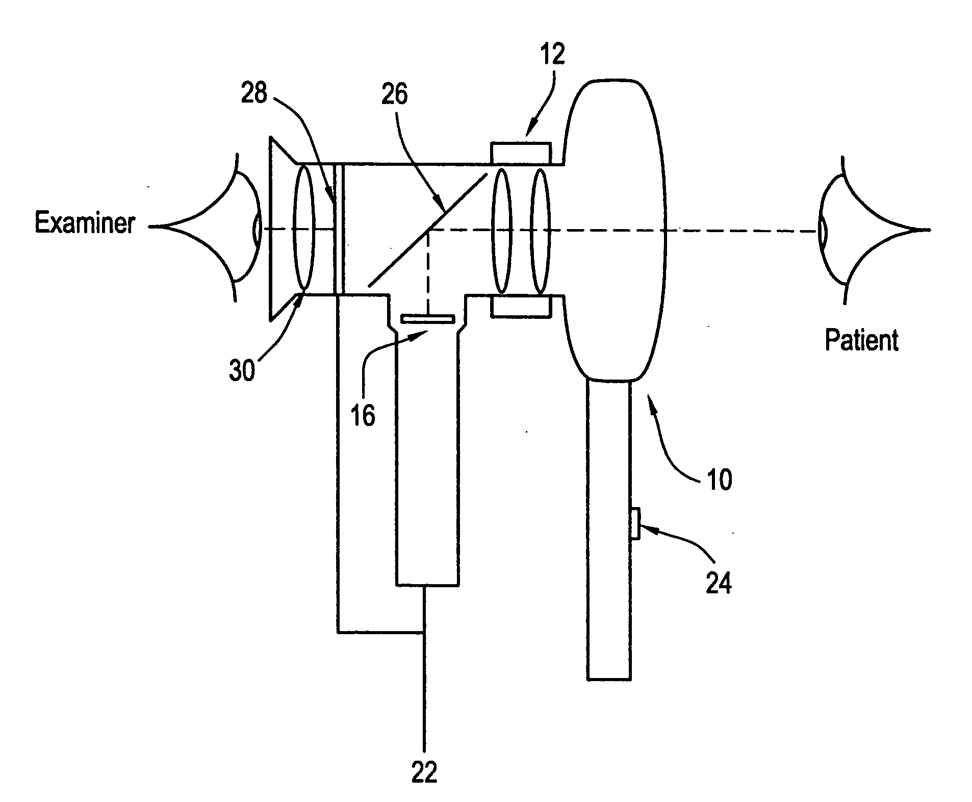
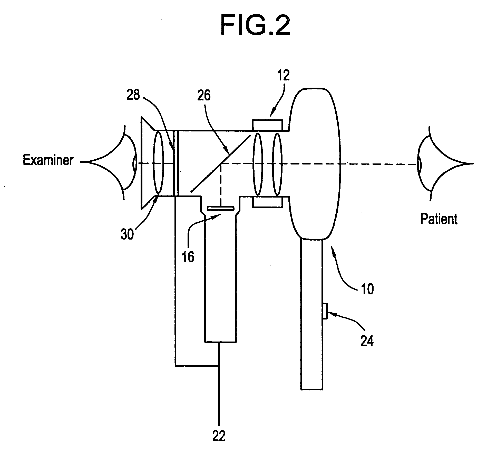
[0027] In a second embodiment, as shown in FIG. 2, the examiner is able to view the output of the imager 16 directly. This is accomplished by replacing the beam-splitter assembly with a simple folding mirror 26 and mounting a miniature liquid crystal display (LCD) 28 and display viewing optics 30 where the physician would ordinarily place his eye on the ophthalmoscope. The light from the patient's eye is reflected by mirror 26 to form a first image on imager, 16, e.g., a CCD array. The output of the imager 16 is then sent to the LCD 28 to form a second image. Thus, the examiner by viewing the second image will be able to see the quality of the first image captured by the imager 16 and can compensate for poor image quality by adjusting the focus using lens system 12. Thus, the examiner is able to focus both first and second images simultaneously. The fine focus of lens system 12 can be automated.

third embodiment

[0028] In a third embodiment as shown in FIG. 3, an additional optics / detection system is incorporated to effect an automatic focusing thus relieving the physician of the focusing operation for the imager 16. The lens system 12, minus the focusing wheel (not shown separately) which remains in its original position, has been moved although it could be retained in its original position as shown in FIGS. 1 and 2. The beam splitter allows the examiner to view the patient's eye directly while also causing light to pass through the lens system 12 and a partial reflector 32 to form a first image on CCD 16. The partial reflector also sends light to mirror 34 which sends the light through lenslet array 36 to form a second image on a linear CCD array 38. The output from the linear CCD array is then sent through a difference amplifier 40 to form an error signal which is sent to lens system 12 through feedback loop 42. Such a system will judge if the image is sharp (in focus) based upon well-un...


PUM


Abstract

A hand-held ophthalmoscope modified by the removal or augmentation of the focusing wheel and the addition of a manual or automatic focusing lens system. An electronic imager (CCD array or video camera) is placed optically conjugate to a viewing screen such that focus operations performed by the examiner to adjust the image seen by the examiner on the screen also focuses the image on the electronic imager. This is accomplished by an optical system which includes a straight path from the viewing screen to the patient's eye with a beam splitter interposed to cause the image of the patient's eye to be reflected onto the imager. As a result, when the examiner uses the focusing lens system, manual or automatic, positioned between the beam splitter and the patient's eye, to affect the image viewed by the examiner, the focus of the imager is simultaneously affected as well. Alternatively, the image from the imager is sent to a liquid crystal display (LCD) in the instrument's eye piece; when the examiner focuses the image on the LCD, the image on the imager is focused simultaneously. Also provided is an automatic focusing system for the imager that operates independently of the examiner's focusing adjustments. An automatic focusing system for the imager can also be incorporated in the other two embodiments. The output from the electronic imager can be in digital or analog form and can consist of a single frame or a video stream.

Description

CROSS-REFERENCE TO RELATED APPLICATION [0001] This is a divisional of prior filed copending application Ser. No. 10 / 351,879, filed Jan. 27, 2003, now abandoned, which in turn is a divisional of prior filed copending application Ser. No. 09 / 370,646, filed Aug. 6, 1999, issued as U.S. Pat. No. 6,511,420, on Jan. 28, 2003, which claims the benefit of prior filed copending U.S. provisional application Ser. No. 60 / 095,534, filed Aug. 6, 1998.BACKGROUND OF THE INVENTION [0002] 1. Field of the Invention [0003] This invention relates generally to medical diagnostic instruments and, more specifically, to a hand-held opto-diagnostic instrument, e.g., an ophthalmoscope or an otoscope, modified so that a video image generated by the instrument is in proper focus. In some embodiments, fine focus adjustments performed by an examiner (physician or physician's assistant), or automatically by the instrument for the examiner, simultaneously focus the video image generated by the instrument. The inven...

Claims


Application Information

Patent Timeline
IPC IPC(8): A61B3/14
CPCA61B3/145
Inventor FARRELL, RICHARD A.HAPPEL, LORENZ J. JR.MCCALLY, RUSSELL L.DUNCAN, DONALD D.BALDWIN, KEVIN C.
Owner FARRELL RICHARD A
Why Eureka
Try Eureka