Detector module and radiation imaging apparatus
a technology of radiation imaging apparatus and detector module, which is applied in the direction of optical radiation measurement, instruments, applications, etc., can solve the problems of time and effort over imaging preparation, inaccurate correction of subject data,
- Summary
- Abstract
- Description
- Claims
- Application Information
AI Technical Summary
Benefits of technology
Problems solved by technology
Method used
Image
Examples
first embodiment
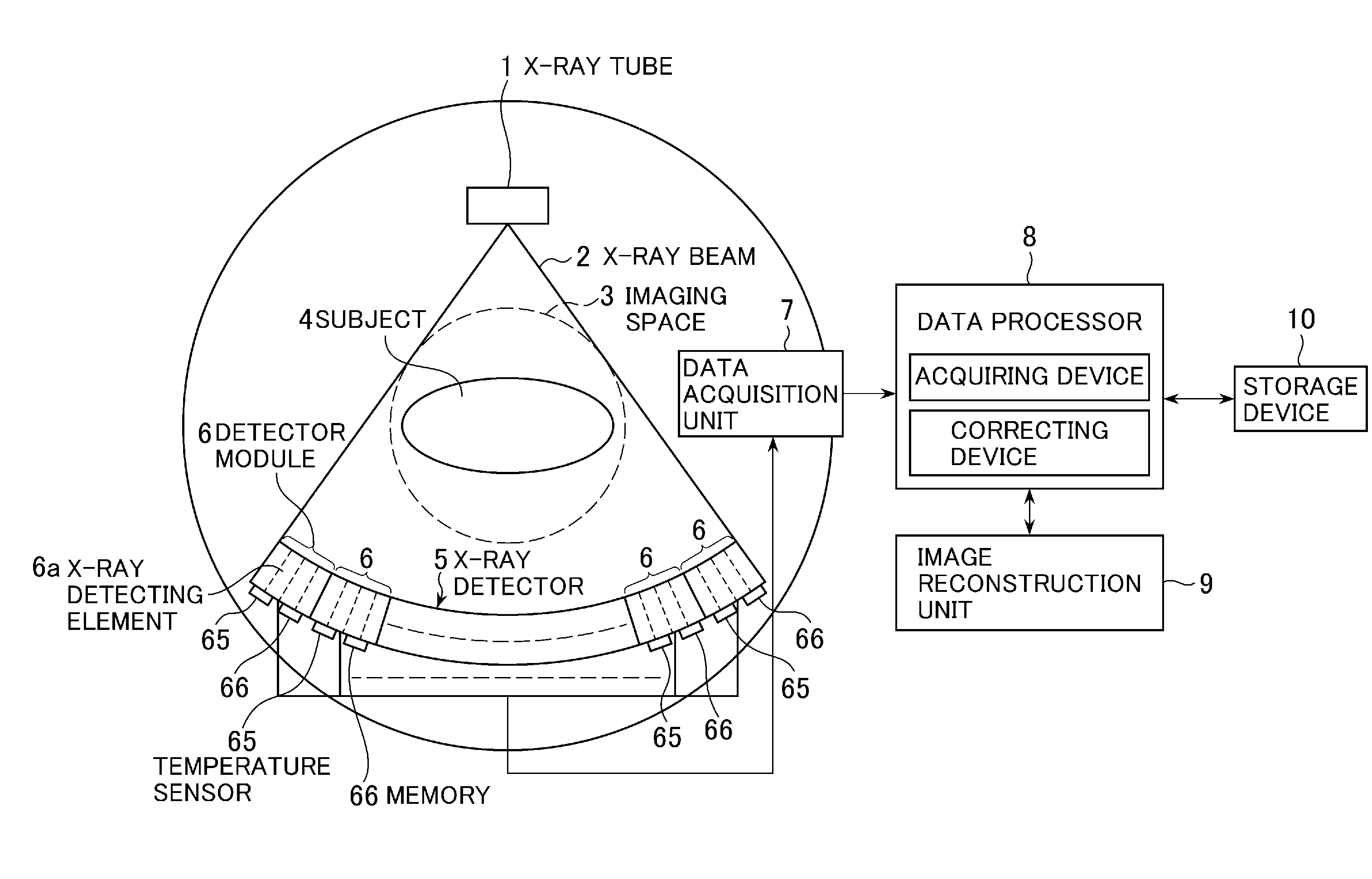
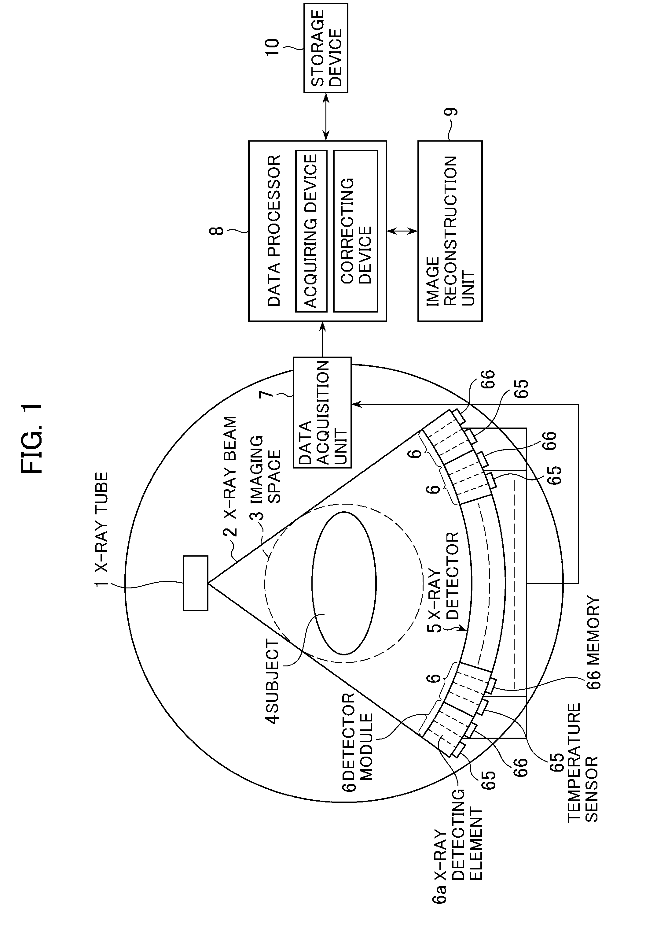
[0036]FIG. 1 is a schematic configuration diagram of an X-ray CT apparatus. As shown in FIG. 1, the X-ray CT apparatus is equipped with an X-ray tube 1, an X-ray detector 5, a data acquisition unit 7, a data processor 8, an image reconstruction unit 9 and a storage device 10.
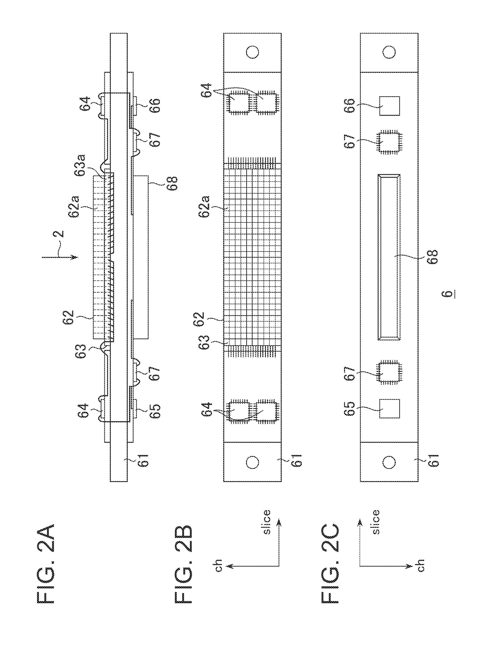
[0037]The X-ray tube 1 and the X-ray detector 5 are disposed opposite to each other with an imaging space 3 interposed therebetween and supported rotatably around the imaging space 3. The X-ray tube 1 projects an X-ray beam 2 to the X-ray detector 5. The X-ray detector 5 is configured by a plurality of detector modules 6 disposed therein. The detector modules 6 include a plurality of X-ray detecting elements 6a respectively. X-ray incident planes of the X-ray detecting elements 6a are arranged in matrix form. The X-ray detector 5 detects X-rays penetrated through a subject 4 to be imaged placed in the imaging space 3, by the X-ray detecting elements 6a and outputs projection data that are their detected data. At...
second embodiment
[0077]FIG. 4 is a diagram showing a schematic configuration of an X-ray CT apparatus according to a second embodiment.
[0078]In the second embodiment, the X-ray CT apparatus has a reading unit 11 of a storage medium. A storage medium 12 readable by the reading unit 11 stores therein temperature characteristic data of each detector module 6. The temperature characteristic data is determined by a prescribed method and stored in the storage medium 12 outside the X-ray CT apparatus. The storage medium 12 is managed as a set by attachment to each detector module 6 or the like. A data processor 8 of the X-ray CT apparatus reads and acquires the temperature characteristic data stored in the storage medium 12 through the reading unit 11. As the storage medium 12, there are various media such an IC card equipped with an IC chip, printed matters such as a bar code, a QR code and the like in addition to optical discs such as a CD-ROM, a DVD-ROM, etc., a magnetic disc such as an FD (Flexible Dis...
third embodiment
[0081]FIG. 5 is a diagram showing a schematic configuration of an X-ray CT apparatus according to a third embodiment.
[0082]In the third embodiment, the X-ray CT apparatus is connected to a database 13 through a network. The database 13 stores temperature characteristic data of each detector module 6 therein. The temperature characteristic data is determined by a prescribed method in advance and stored in the database 13 outside the X-ray CT apparatus. A data processor 8 of the X-ray CT apparatus identifies the individual detector modules 6 that configure an X-ray detector 5 and reads and acquires the temperature characteristic data corresponding to the identified detector modules 6 from the database 13. The location to provide the database 13 is not limited in particular. The network is irrespective of whether or not it is wired or wireless. Incidentally, the database 13 is one example of a storing device. The data processor 8 is one example illustrative of an acquiring device and a...
PUM
| Property | Measurement | Unit |
|---|---|---|
| temperature | aaaaa | aaaaa |
| temperature | aaaaa | aaaaa |
| storing temperature | aaaaa | aaaaa |
Abstract
Description
Claims
Application Information
 - R&D
- Intellectual Property
- Life Sciences
- Materials
- Tech Scout
- Unparalleled Data Quality
- Higher Quality Content
- 60% Fewer Hallucinations
Browse by: Latest US Patents, China's latest patents, Technical Efficacy Thesaurus, Application Domain, Technology Topic, Popular Technical Reports.
© 2025 PatSnap. All rights reserved.Legal|Privacy policy|Modern Slavery Act Transparency Statement|Sitemap|About US| Contact US: help@patsnap.com


