Hydrogen generator with a combustor with a control unit

a technology of control unit and hydrogen generator, which is applied in the direction of combustion control, sustainable manufacturing/processing, instruments, etc., can solve the problems of affecting the operation of the hydrogen generator, reducing the catalytic activity, and clogging of the gas passage, so as to increase the temperature of the evaporator and reduce the time taken

Inactive Publication Date: 2011-11-01
PANASONIC CORP
View PDF10 Cites 0 Cited by
  • Summary
  • Abstract
  • Description
  • Claims
  • Application Information

AI Technical Summary

Benefits of technology

[0024]In the case of increasing the temperature of the evaporator to the water-evaporable temperature while, by repeating ON and OFF of the combustion operation of the combustor in the start-up operation of the hydrogen generator, maintaining the temperature of the reforming catalyst to a temperature lower than the temperature at which the carbon deposition of the raw material occurs, the hydrogen generator of the present invention can make the time taken to increase the temperature of the evaporator shorter than the hydrogen generator of the conventional example, and can make the time taken to start up the hydrogen generator shorter than the hydrogen generator of the conventional example. In addition, the hydrogen generator of the present invention can reduce the number of times of ON and OFF of the combustion operation of the combustor, reduce the load with respect to the combustor and igniting portion of the hydrogen generator, and improve the durability of the structure.

Problems solved by technology

When the amount of steam supplied to the reforming catalyst layer in the reforming reaction is inadequate as compared to the amount of the raw material supplied, only the raw material increases in temperature, and flows through the catalyst layer in the reformer and gas passages.
This may cause a decrease in catalytic activity and clogging of the gas passages, thereby disturbing the operation of the hydrogen generator.

Method used


Image

  • Hydrogen generator with a combustor with a control unit
  • Hydrogen generator with a combustor with a control unit
  • Hydrogen generator with a combustor with a control unit

Examples


embodiment 1

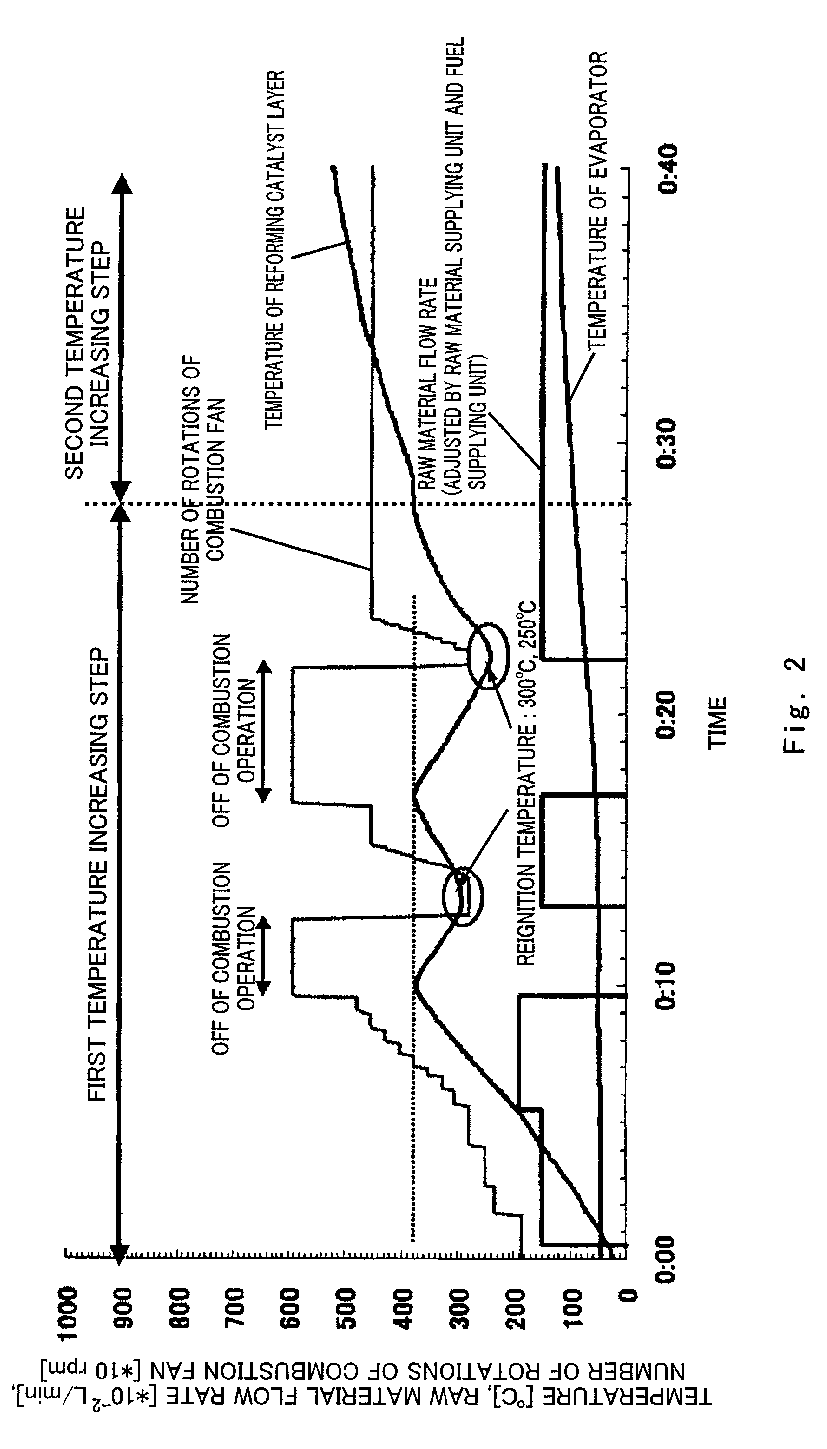
[0051]Hereinafter, Embodiment 1 will be explained in reference to the drawings.

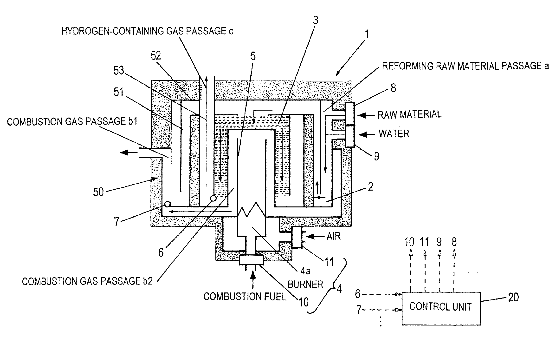
[0052]FIG. 1 is a schematic cross-sectional view showing the configuration of a hydrogen generator according to Embodiment 1 of the present invention, and especially shows in detail a reformer, i.e., a main component of a hydrogen generator 1, and its surrounding components.

[0053]As shown in FIG. 1, the hydrogen generator 1 is constituted by a cylindrical main body 50 whose upper and lower ends are closed, and includes: a raw material supplying unit 8 which adjusts the amount of raw material which is comprised of an organic compound containing carbon and hydrogen and supplied to a reformer including a reforming catalyst layer 3; a water supplying unit 9 which adjusts the amount of water supplied to the reformer; a combustor 4 which heats the reformer; a fuel supplying unit 10 which adjusts the amount of combustion fuel supplied to the combustor 4; an air supplying unit 11 which adjusts the amount of air s...

embodiment 2

[0105]Hereinafter, Embodiment 2 will be explained in reference to the drawings.

[0106]FIG. 6 is a schematic block diagram showing the configuration of the fuel cell system according to Embodiment 2 of the present invention. A fuel cell system 200 includes the hydrogen generator 1 and a fuel cell 101 as main components. The fuel cell 101 is, for example, a polymer electrolyte fuel cell.

[0107]The hydrogen generator 1 is the hydrogen generator 1 of Embodiment 1, but includes a shift converter 30 and a CO remover 31 in addition to the above-described reformer (shown as “reformer 1A” in FIG. 6) and the combustor 4.

[0108]Specifically, the hydrogen-containing gas passage c of FIG. 1 is connected to the shift converter 30, and the shift converter 30 and the CO remover 31 are connected to each other by a hydrogen-containing gas passage d. In the hydrogen generator 1 configured as above, the hydrogen-containing gas generated by the reforming catalyst layer 3 is supplied to the shift converter ...


PUM

PropertyMeasurementUnit
temperatureaaaaaaaaaa

Abstract

A hydrogen generator (1) includes: a reformer which generates a hydrogen-containing gas from a raw material and steam; a combustor (4) which heats the reformer; an evaporator (2) which generates the steam by utilizing heat of a combustion gas after the reformer is heated by the combustion gas; and a control unit (20), the hydrogen generator (1) is controlled such that ON and OFF of a combustion operation of the combustor (4) are repeated in a start-up operation of the hydrogen generator (1) and a temperature of the reformer is kept to a predetermined temperature or lower, and the control unit (20) controls the combustion operation such that a heat amount per unit time by the combustor (4) in a first combustion operation is larger than the heat amount per unit time in k-th (k>1) and following combustion operations.

Description

RELATED APPLICATIONS[0001]This application is the US National Phase under 35 U.S.C. §371 of International Application No. PCT / JP2007 / 62121 filed on Jun. 15, 2007, which claims the benefit of Japanese Application No. JP 2006-165855 filed on Jun. 15, 2006, the disclosures of which Applications are incorporated by reference herein.TECHNICAL FIELD[0002]The present invention relates to a hydrogen generator which generates a hydrogen-containing gas by a steam-reforming reaction using as a main raw material a hydrocarbon-based material, such as natural gas, LPG; gasoline, naphtha, kerosene, or methanol, and a fuel cell system including the hydrogen generator.BACKGROUND ART[0003]In the hydrogen generator, a raw material containing an organic compound comprised of at least carbon and hydrogen is subjected to steam reforming by a reformer including a reforming catalyst layer. A hydrogen-containing gas is generated by this reforming reaction. When the amount of steam supplied to the reforming ...

Claims


Application Information

Patent Timeline
Patent Type & Authority Patents(United States)
IPC IPC(8): H01M8/06
CPCC01B3/384F23N5/20H01M8/04022H01M8/04268H01M8/0612C01B2203/0233C01B2203/066C01B2203/0816C01B2203/0822C01B2203/0827C01B2203/0894C01B2203/1604F23C2900/03002F23N2027/02F23N2037/10Y02E60/50F23N2227/02F23N2237/10Y02P20/10
Inventor TAMURA, YOSHIOTAGUCHI, KIYOSHINAKAMURA, AKINARIOHARA, HIDEOOZEKI, MASATAKA
Owner PANASONIC CORP
Why Eureka
Try Eureka