Apparatus for displaying image by projection on retina of viewer with eliminated adverse effect of intervening optics

a technology of image projection and retina, applied in the field of apparatus for projecting images onto the retina, can solve the problems of affecting the perception accuracy of images,

Inactive Publication Date: 2005-10-20
BROTHER KOGYO KK
View PDF10 Cites 37 Cited by
  • Summary
  • Abstract
  • Description
  • Claims
  • Application Information

AI Technical Summary

Benefits of technology

[0010] Such a type of an image display apparatus, when practiced, allows a viewer to visually perceive that a luminance point (a light emission point) is positioned at a point obtained by extending back a light beam incident on the retina o

Problems solved by technology

However, when the aforementioned conventional image display apparatus is practiced using the aforementioned optics which is disclosed in the aforementioned Japanese Patent Publication as having the aforementioned shape, the ununiformity in curvature of the reflective surface of the optics causes the amount or degree of change in wavefront curvature (the amount of deviation of the wavefront curvature) of the laser light between before and after reflection by the reflective surface, to be varied with changes in entrance position (reflection position) at which the laser light enters the refle

Method used


Image

  • Apparatus for displaying image by projection on retina of viewer with eliminated adverse effect of intervening optics
  • Apparatus for displaying image by projection on retina of viewer with eliminated adverse effect of intervening optics
  • Apparatus for displaying image by projection on retina of viewer with eliminated adverse effect of intervening optics

Examples


first embodiment

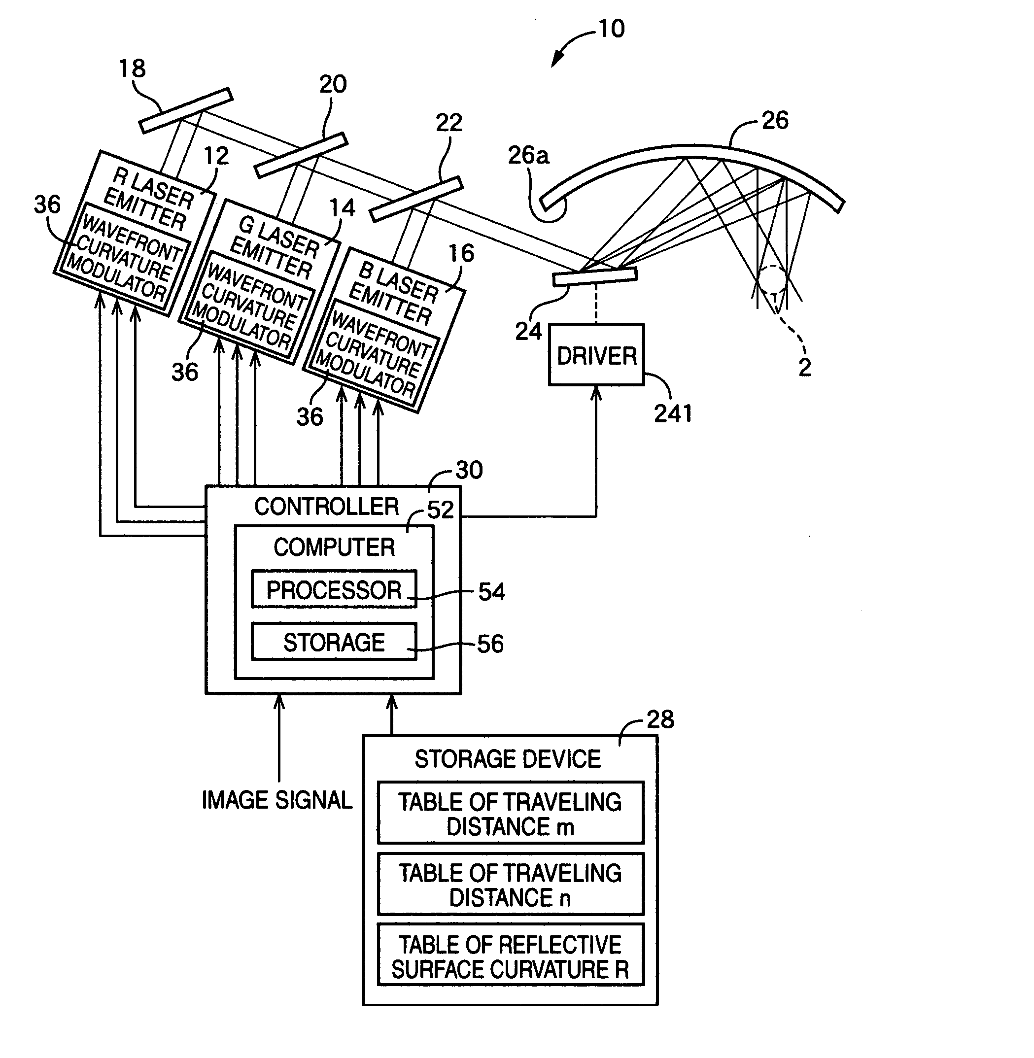
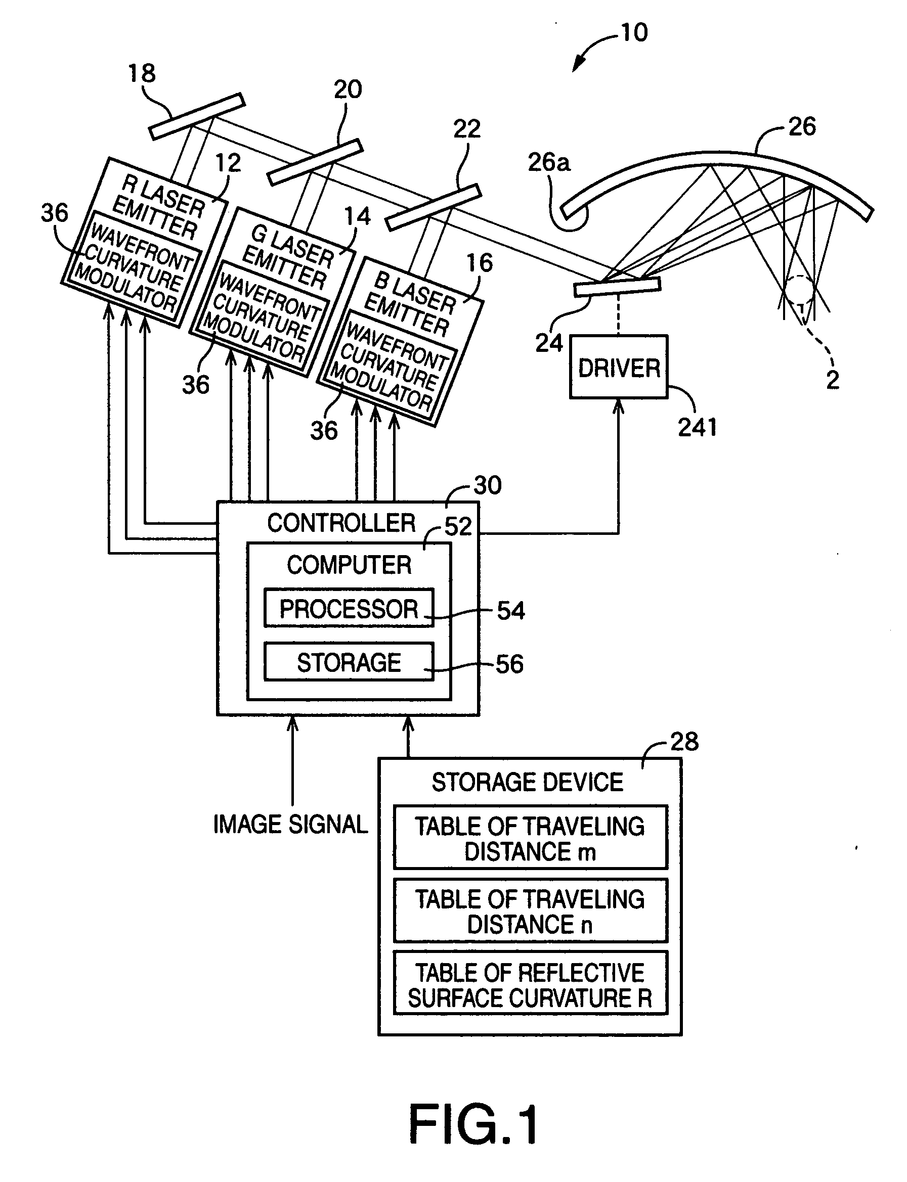
[0140]FIG. 1 shows a schematic configuration of a retinal scanning display 10 as an image forming apparatus in accordance with the present invention.

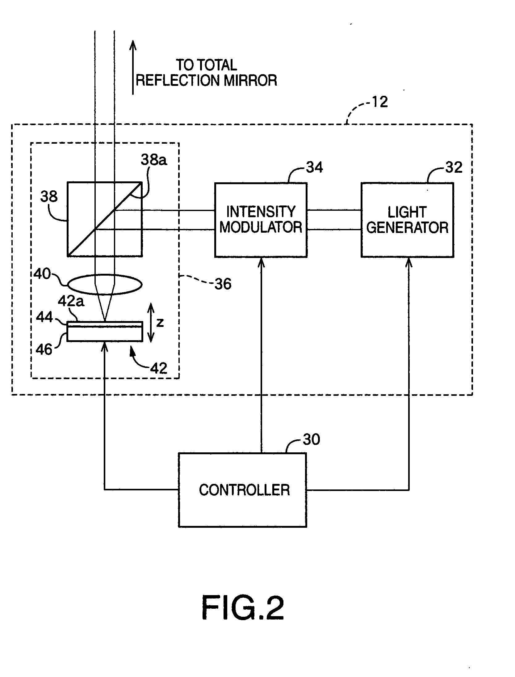
[0141] The retinal scanning display 10 is for use in causing laser light in the form of a light beam to enter a pupil 2 of a viewer's eye, to thereby allow the viewer to perceive an image projected onto a retina of the viewer's eye. The retinal scanning display 10, as shown in FIG. 1, includes an R laser emitter 12, a G laser emitter 14, and a B laser emitter 16, each of which emits laser light of a corresponding one of red (R), green (G), and blue (B) (having the respective different wavelength bands), and each of which is capable of modulating the output intensity and the wavefront curvature of the corresponding laser light emitted.

[0142] As shown in FIG. 1, the retinal scanning display 10 further includes a total reflection mirror 18 and partially-transmissible mirrors 20, 22, both utilized for combining the laser light of three col...

second embodiment

[0241] Next, there will be described with reference to FIG. 10 a retinal scanning display 60 as an image display apparatus constructed according to the present invention.

[0242] As illustrated in FIG. 10, the retinal scanning display 60 according to the present embodiment includes a temperature sensor 62 in addition to the common components to those of the retinal scanning display 10 according to the first embodiment.

[0243] Further, the retinal scanning display 60 according to the present embodiment is configured such that the storage device 28 has stored therein a plurality of table sets, each table set including a set of the tables for the traveling distances “m” and “n” and the reflective surface curvature “R,” respectively.

[0244] The present embodiment will be described in greater detail below, while the common components to the retinal scanning display 10 illustrated in FIG. 1 will be omitted in the detailed description with the common components being referenced the identical...

third embodiment

[0257] Next, there will be described with reference to FIG. 11 a retinal scanning display 70 as an image display apparatus constructed according to the present invention.

[0258] As illustrated in FIG. 11, the retinal scanning display 70 according to the present embodiment is common in fundamental construction to the retinal scanning display 10 according to the first embodiment.

[0259] However, in the present embodiment, as opposed to the first embodiment, an active projection mirror 26 is selected from a plurality of candidate projection mirrors different in kind, allowing replacement in kind of the projection mirror 26. Along with this, in the present embodiment, a replacement entry switch 72 is provided which is to be manipulated by the viewer for replacement in kind of the projection mirror 26.

[0260] Further, the retinal scanning display 70 according to the present embodiment is configured such that, similarly with the second embodiment illustrated in FIG. 10, the storage device ...


PUM


Abstract

An apparatus for use in image display, of projecting a light beam onto a retina of a viewer, to thereby allow the viewer to perceive an image, is disclosed. The apparatus is constructed to include: a light emitter emitting a light beam; a scanner scanning the light beam emitted by the light emitter; an optical system receiving the light beam scanned by the scanner as an incoming light beam, and emitting the received incoming light beam as an outgoing light beam, such that, upon modulation of the light beam with respect to a traveling direction of the light beam, the outgoing light beam is directed to a pupil of the viewer; and a curvature compensator compensating a wavefront curvature of the incoming light beam.

Description

[0001] This application is based on Japanese Patent Application No. 2002-344008 filed Nov. 27, 2002, and PCT International Application No. PCT / JP2003 / 14228 filed Nov. 7, 2003, the contents of which are incorporated hereinto by reference. CROSS-REFERENCE TO RELATED APPLICATIONS [0002] This is a continuation of International Application PCT / JP2003 / 14228 filed Nov. 7, 2003, which was published in Japanese under PCT Article 21(2).BACKGROUND OF THE INVENTION [0003] 1. Field of the Invention [0004] The invention relates to an apparatus for projecting an image onto the retina of a viewer's eye thereby allowing the viewer to perceive the image. [0005] 2. Description of the Related Art [0006] There have been recently presented various types of image display apparatuses each projecting an image by scanning a light beam on the retina of a viewer's eye to thereby allow the viewer to perceive the image, which are each called, “Retinal Scanning Display.”[0007] For example, Japanese Patent Publica...

Claims


Application Information

Patent Timeline
IPC IPC(8): G02B26/06G02B27/01G09G3/00H04N9/31
CPCG02B26/06G02B27/01H04N9/3129G09G3/002G02B27/0101
Inventor WATANABE, MITSUYOSHIYAMADA, SHOJI
Owner BROTHER KOGYO KK
Why Eureka
Try Eureka