

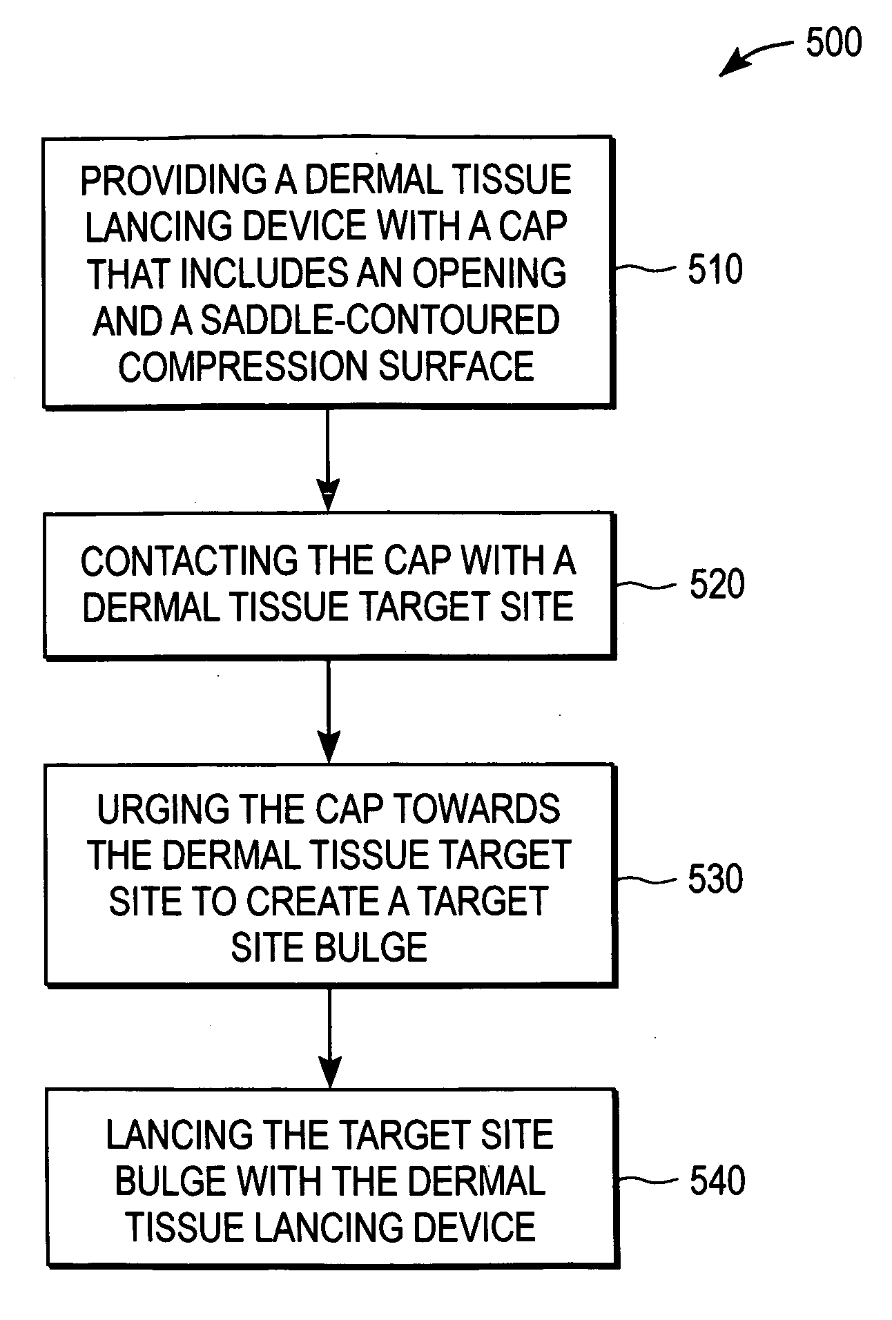
Method for lancing a dermal tissue target site
a dermal tissue and target site technology, applied in the field of lancing methods, can solve the problems of inconvenient use, high manufacturing cost of devices, and inability to reliably produce adequate volume of biological fluid samples, and achieve the effect of uniform pressure application
- Summary
- Abstract
- Description
- Claims
- Application Information
AI Technical Summary
Benefits of technology
Problems solved by technology
Method used
Image

Examples
Embodiment Construction
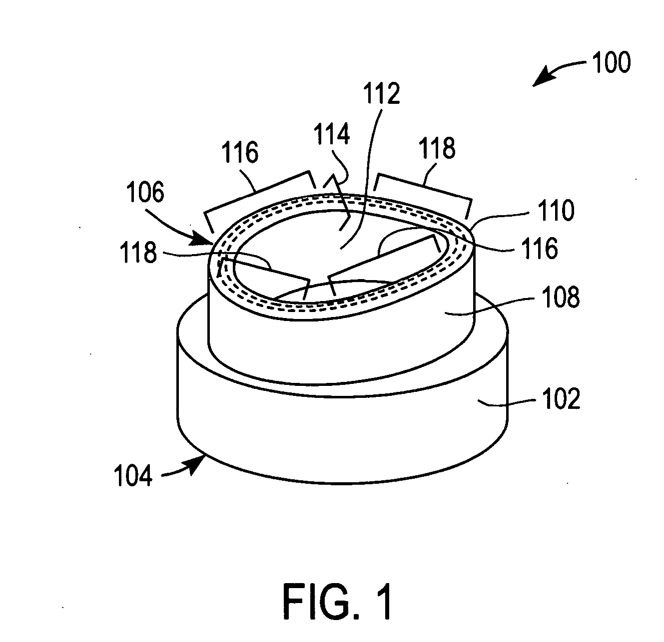
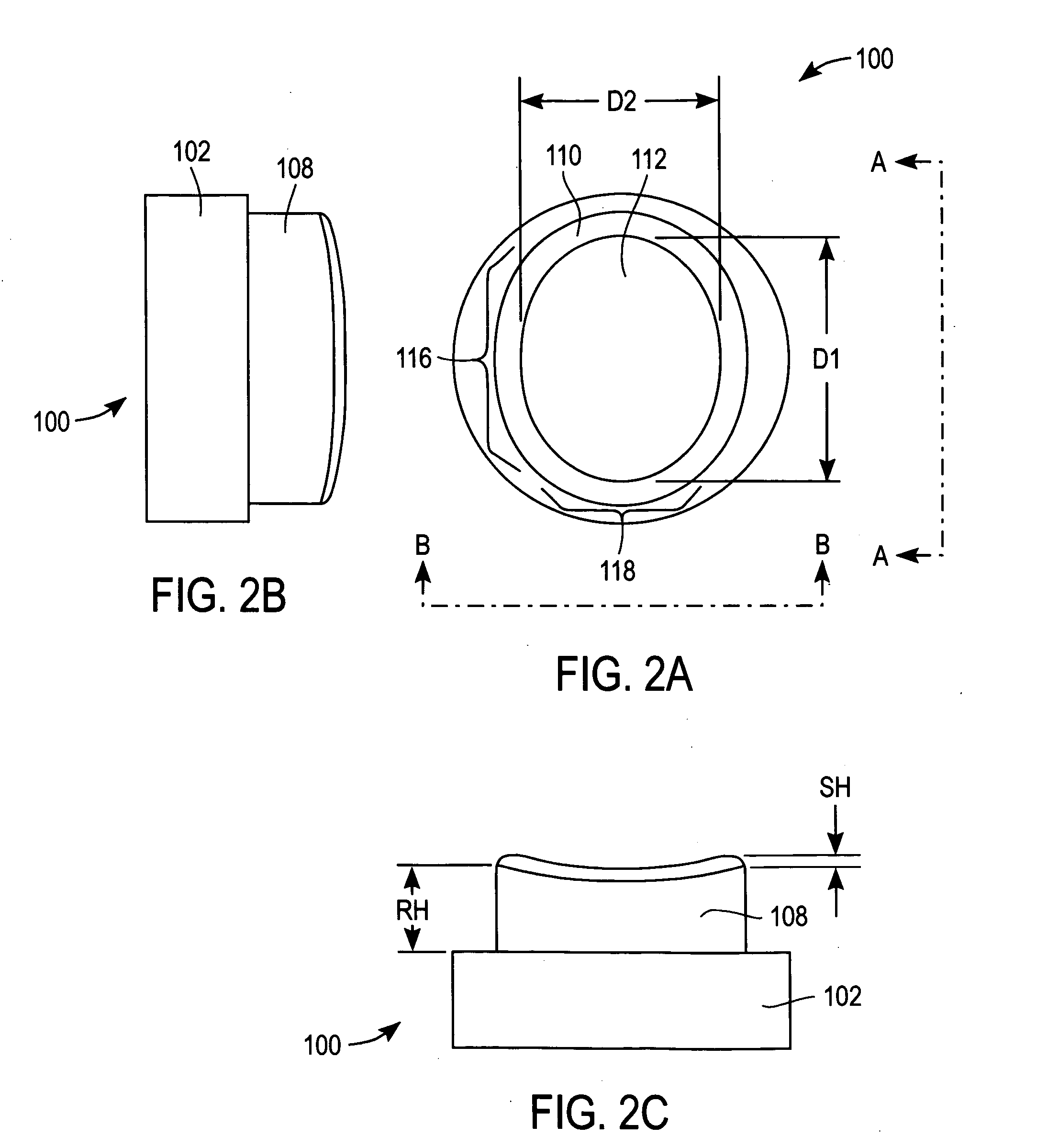
[0024]FIG. 1 is a simplified perspective view of a cap 100 for use with a dermal tissue lancing device (not shown) according to an exemplary embodiment of the present invention. Cap 100 includes a body 102 with a proximal end 104 and a distal end 106.
[0025] Cap 100 is configured to facilitate the flow of a biological fluid sample (e.g., a whole blood sample) out of a lanced dermal tissue target site with minimal or no manipulation (e.g., squeezing and / or milking) of the dermal tissue subsequent to lancing.
[0026] Proximal end 104 is configured to be removeably attached to an end of a dermal tissue lancing device (not shown) by, for example, slideably mounting, snap-fitting or screw-fitting proximal end 104 to the end of the dermal tissue lancing device. Alternatively, proximal end 104 of cap 100 can be configured for retention within a retainer (not shown) that is removeably attached to the end of a dermal tissue lancing device.
[0027] Once apprised of the present disclosure, one s...
PUM
| Property | Measurement | Unit |
|---|---|---|
| length | aaaaa | aaaaa |
| length | aaaaa | aaaaa |
| height | aaaaa | aaaaa |
Abstract
Description
Claims
Application Information