Rotary Valve Seal Pressure and Indicator System

a technology of indicator system and seal pressure, which is applied in the direction of spindle sealing, conveying, transportation and packaging, etc., can solve the problems of air leakage, uneven flow of particulate materials, and improper adjustment of seals, so as to achieve the effect of quick adjustment of the cartridg

Inactive Publication Date: 2017-01-05
PRATER INDS
View PDF11 Cites 2 Cited by
  • Summary
  • Abstract
  • Description
  • Claims
  • Application Information

AI Technical Summary

Benefits of technology

[0014]It is a further object of the invention to provide the ability to vary the cartridge spring pressure to allow for adjustment of the pressure applied by the cartridge to accommodate different

Problems solved by technology

Because the interior of the valve may be pressurized, and because the valve assemblies are subject to continuous use, air leakage and improper adjustment of the seals is a common problem.
In severe cases, leakage of air around or past the housing seals can degrade the performance of the valve assembly, affecting the differential pressures required to be maintained within the system, and resulting in uneven flow of the particulate material.
Acc

Method used


Image

  • Rotary Valve Seal Pressure and Indicator System
  • Rotary Valve Seal Pressure and Indicator System
  • Rotary Valve Seal Pressure and Indicator System

Examples


Embodiment Construction

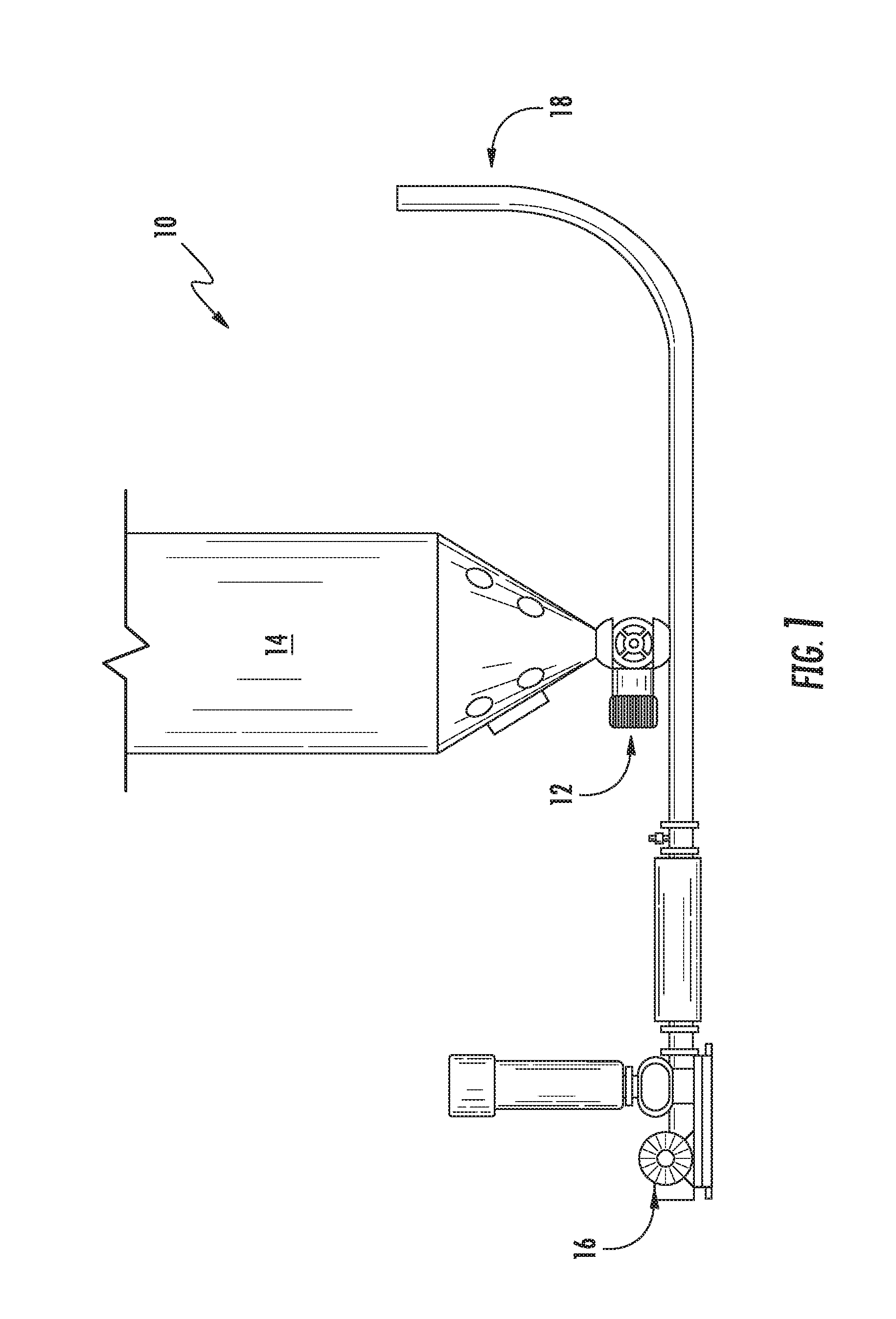
[0029]The significance of the present invention will best be appreciated by first referring to FIG. 1. In the typical environment for the conveyance of dry, free-flowing powders, granules, crystals, pellets and the like, a conveying system is provided. The conveying system 10 of the present invention utilizes a rotary valve 12 to control the flow of particulate material from a storage vessel 14 (e.g., storage source) into a conduit 18, under the influence of air pressure provided by a blower 16. It is desirable to insure that the air pressure provided by the blower 16 is utilized to efficiently move the particulate matter into and through conduit 18, and to minimize air leakage from the rotary valve 12 into the storage vessel 14, and to likewise minimize leakage of air and particulate matter from the rotary valve 12 into the surrounding environment.

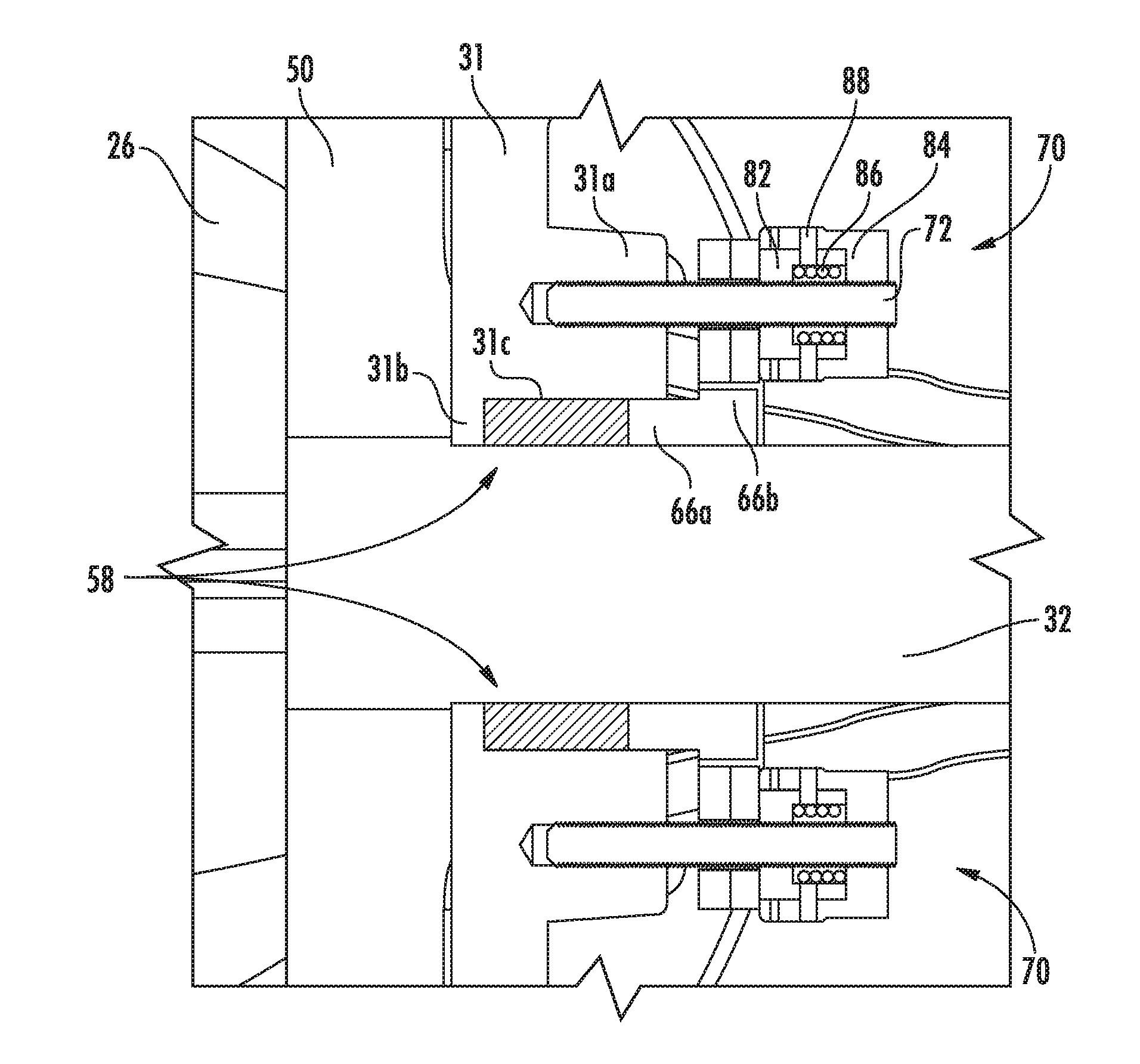
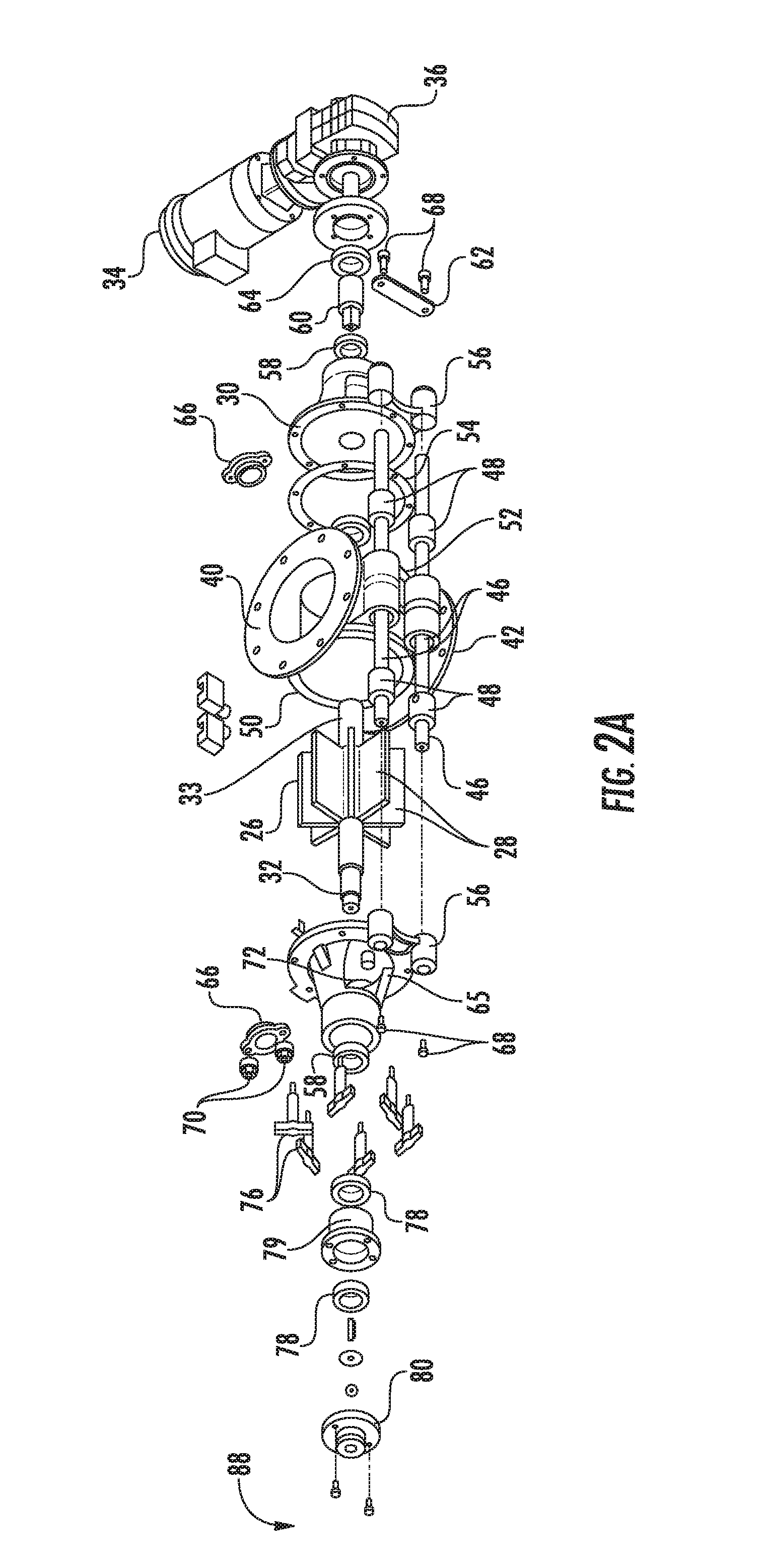
[0030]Referring now to FIGS. 2A-2C, the principal components of the rotary valve 12 of the present invention are depicted. The rotary va...


PUM


Abstract

A rotary valve is configured to control flow of particulate matter from a storage source into a conduit under pneumatic pressure. The valve comprises a cylindrical housing, opposing end plates partially enclosing said cylindrical housing, and a vaned rotor having opposing shafts protruding through annular seals provided in said end plates. At least one spring-loaded cartridge is adapted to exert a pre-determined pressure against said annular seals.

Description

CROSS-REFERENCE TO RELATED APPLICATION(S)[0001]This application claims priority to and the benefit of U.S. Provisional Application No. 62 / 186,522, filed Jun. 30, 2015, the entire disclosure of which is hereby incorporated by reference herein.FIELD OF THE INVENTION[0002]The invention pertains to improvements in rotary airlock valves, and in particular, to devices for applying even sealing forces within the seal system assembly of said valves.BACKGROUND OF THE INVENTION[0003]Rotary valves for the transmission of dry particulate material are well known in the art. Rotary valves facilitate the transmission of a metered flow of dry particulate material into gravity fed or pressurized pneumatic conveying systems. Such conveying systems typically utilize gravity together with a flow of pressurized air through a conduit, thereby establishing a fluidized flow of material into the conduit, thereby moving the particulate material from one place to another.[0004]Rotary valves typically include ...

Claims


Application Information

Patent Timeline
IPC IPC(8): F16K41/02
CPCB65G53/4633F16J15/186
Inventor BOSCARINO, WILLIAM
Owner PRATER INDS
Why Eureka
Try Eureka