Control system, control program product, control method, and control apparatus

a control system and control program technology, applied in the direction of digital output to print units, instruments, electric digital data processing, etc., can solve the problem that data which cannot be processed by the printer cannot be printed out by the printer, and achieve the effect of suppressing an increase in cos

Inactive Publication Date: 2005-10-20
SEIKO EPSON CORP
View PDF4 Cites 38 Cited by
  • Summary
  • Abstract
  • Description
  • Claims
  • Application Information

AI Technical Summary

Benefits of technology

[0021] With the control method, it is possible to link the devices which are connected to the network and different from each other in data format of data to treat. Further, in the case where each of plural users link the devices by the use of a control apparatus owned by the user, it is unnecessary for each of the control appa...

Problems solved by technology

However, since the devices can be provided by different manufacturers, a data format of data transmitted from one device is not always in a data format which is processable by another device.
Therefore, the devices to be linked must treat data identical in data fo...

Method used


Image

  • Control system, control program product, control method, and control apparatus
  • Control system, control program product, control method, and control apparatus
  • Control system, control program product, control method, and control apparatus

Examples


first embodiment

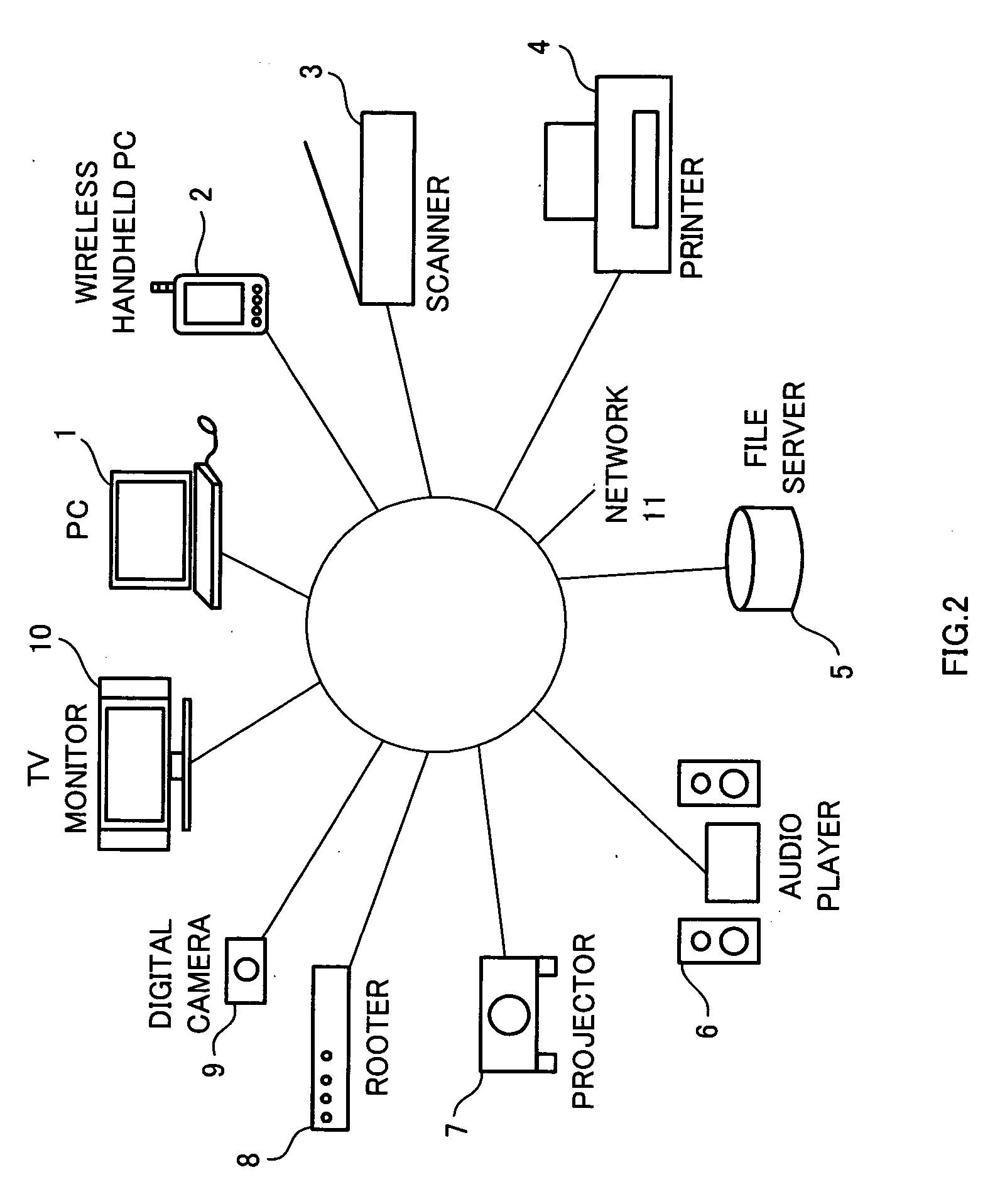
[0038] A control system according to the first embodiment of this invention is a UPnP control point such as a PC (Personal Computer) 1 shown in FIG. 2 or the like. Though the first embodiment will be described by using the PC 1 as an example of the control system, the control apparatus of this invention may be a wireless handheld PC 2, a mobile phone (not shown), or the like. A control program of the first embodiment is executed by the UPnP control point such as the PC 1. Examples of UPnP devices to be connected to a UPnP network11 include a scanner 3, a printer 4, a file server 5, an audio player 6, a projector 7, a rooter 8, a digital camera 9, a TV (Television) monitor 10, and the like.

[0039]FIG. 3 is a block diagram showing a hardware structure of the PC 1 serving as the control system. The PC 1 is provided with a CPU 20, a RAM 21, a hard disk device (HDD) 22, an external interface 23, a ROM 24, a display unit 25, and an operation unit 26. The CPU 20 functions as a detection un...

second embodiment

[0070] The second embodiment is an example of printing out a video stored in a file server.

[0071]FIG. 11 is a diagram showing a transition of screens when PRINT is selected. When PRINT is selected, a screen 400 for selecting a printer, a screen 410 for setting various parameters such as a printing condition, and a screen 420 for selecting a file to be printed out are displayed as shown in FIG. 11. In addition, the screen 420 for selecting a file to be printed may be displayed to start with.

[0072]FIG. 12 is a sequence chart showing a flow of processing of printing a video by the printer.

[0073] In the step S405, the PC 1 receives a command for executing printing. Specifically, a user clicks the print button 102 on the control screen shown in FIG. 6A so that the PC 1 receives the execution command.

[0074] In the step S410, the main module of the control program 31 uses the label of the activated module described in the screen management table to call up a print control module for co...

third embodiment

[0084] The third embodiment is an example of converting data by the use of a third device connected to a network, not by the UPnP control point.

[0085]FIG. 13 is a schematic diagram showing one example of a UPnP device to be connected to a UPnP network 11 of the third embodiment. In the example shown in FIG. 13, a conversion server 12 is connected as the third device in addition to the example shown in FIG. 2. The conversion server 12 is connected in such a fashion as to communicate in accordance with the UPnP protocol, too. A control program executed by the PC 1 of the third embodiment enables the PC 1 to function as a control apparatus, so that the PC 1 requests the conversion server 12 for conversion of data when the data are input to the PC 1.

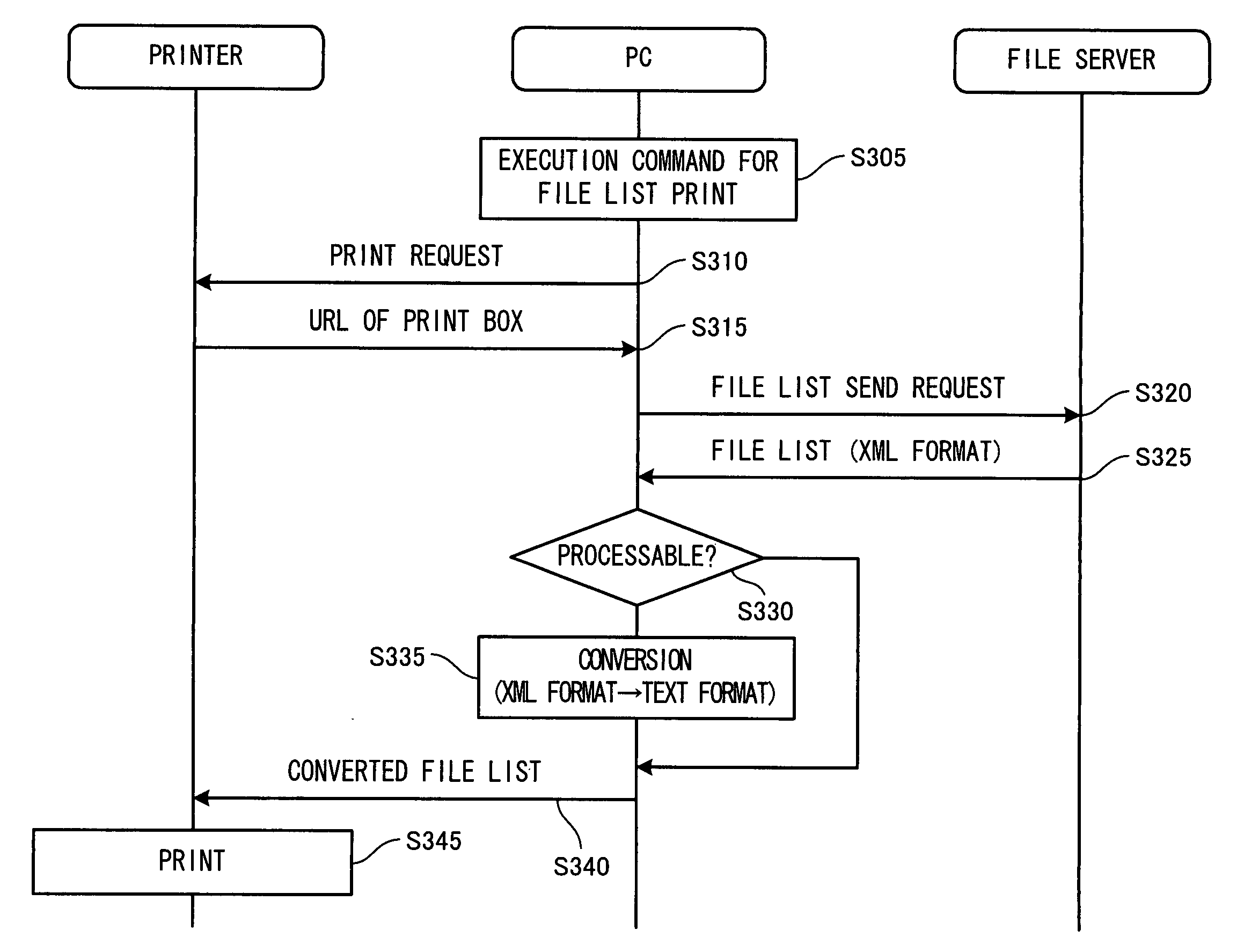
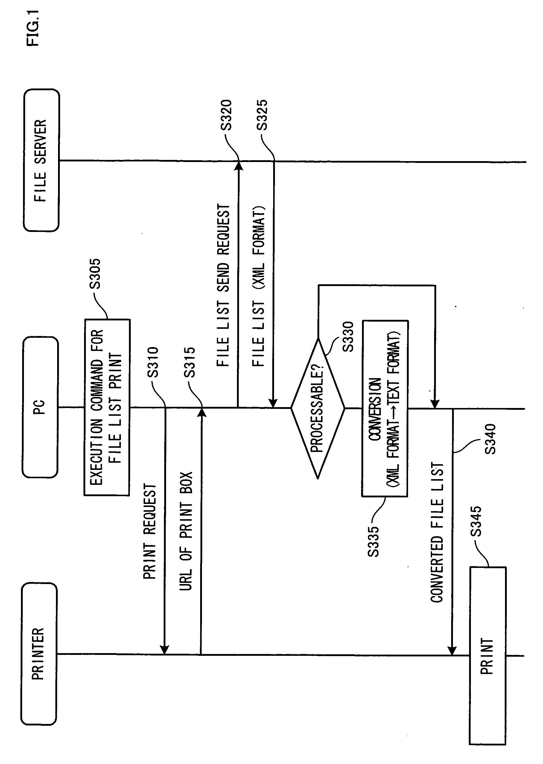
[0086] Hereinafter, a flow of processing of the third embodiment will be described. An example of converting data in XML format into data in text format from which tug information is eliminated will be described.

[0087]FIG. 14 is a sequenc...


PUM


Abstract

A control system comprising: a detection unit for detecting services provided by devices connected to a network; a data input unit for inputting data from a first device detected by the detection unit and providing the service of inputting data; a conversion unit for converting a data format of the data input by the data input unit into a data format processable by a second device detected by the detection unit and providing the service of outputting data; and a service request unit for requesting the second device for a service for the data converted by the conversion unit.

Description

CROSS-REFERENCE TO RELATED APPLICATIONS [0001] The disclosure of Japanese Patent Application No. JP2004-102858 filed on Mar. 31, 2004 including the specification, drawings and abstract is incorporated herein by reference in its entirety. BACKGROUND OF THE INVENTION [0002] 1. Field of the Invention [0003] The present invention relates to a control system, a control program, a control method, and a control apparatus and particularly to an apparatus for integrally controlling various devices connected in a network. [0004] 2. Description of the Related Art [0005] An end-user is generally required to configure complicated settings for setting up peripheral devices in order to put a computer into operation; therefore, it is necessary for the end-user to have basic knowledge about computers. As one of means for solving such problem, UPnP (Universal Plug and Play) is attracting attention. When a network is constituted of a multiple of UPnP devices, it is possible to use a television connect...

Claims


Application Information

Patent Timeline
IPC IPC(8): G06F13/00G06F3/12G06F13/10H04L29/08
CPCH04L67/125H04L67/16H04L67/51
Inventor KUBOTA, TSUKASA
Owner SEIKO EPSON CORP
Why Eureka
Try Eureka