Wireless transceiver system for computer input devices

a transceiver and input device technology, applied in the field of computer systems, can solve the problems of affecting the convenience and value of such devices, the battery life of existing wireless input devices is significantly less than the useful life of such devices, and the range of existing wireless input devices is often limited

Inactive Publication Date: 2005-10-20
JAALAA
View PDF14 Cites 42 Cited by
  • Summary
  • Abstract
  • Description
  • Claims
  • Application Information

AI Technical Summary

Benefits of technology

[0012] A principal object of the present invention is to provide an effective and very manufacturable wireless transceiver system for computer input devices.
[0016] A yet further object of the present invention is to provide a wireless interface device with power saving functions to extend the battery life of the input device.
[0017] A yet further object of the present invention is to provide a wireless interface device with the capability of automatically selecting between several communication frequencies or channels to improve communication reliability and to provide compatibility for various regulatory environments.
[0018] Another further object of the present invention is to provide a wireless interface device with the capability of automatically selecting between several data rates to improve reliability while not sacrificing speed of operation.

Problems solved by technology

Unfortunately, batteries used to power existing wireless input devices typically last for a period of time significantly less than the useful life of such devices.
As a consequence, the convenience and value of such devices are diminished as a consequence of the need for regular battery replacement.
Existing wireless input devices are also frequently of limited range and the wireless link established for communication with the host computer is often rather unreliable and / or exhibits a high latency.
In addition, such wireless links are often relatively insecure and thus susceptible to eavesdropping or unauthorized monitoring.

Method used


Image

  • Wireless transceiver system for computer input devices
  • Wireless transceiver system for computer input devices
  • Wireless transceiver system for computer input devices

Examples


Embodiment Construction

[0053] The preferred embodiments of the present invention disclose wireless transceiver systems for computer devices. In several embodiments, various aspects of unique wireless transceiver systems, useful for operating keyboards and mouse inputs, are disclosed. It should be clear to those experienced in the art that the present invention can be applied and extended without deviating from the scope of the present invention.

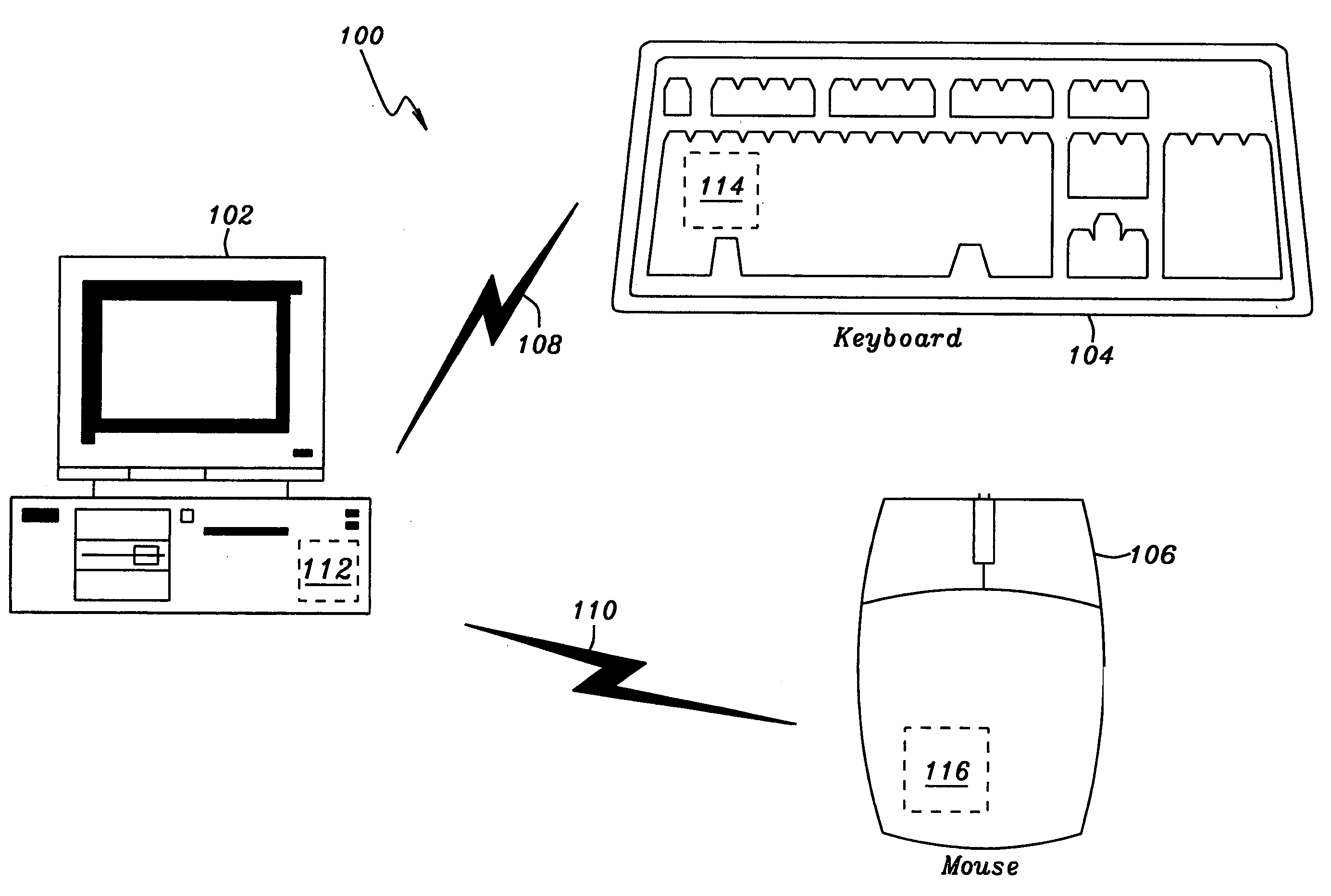
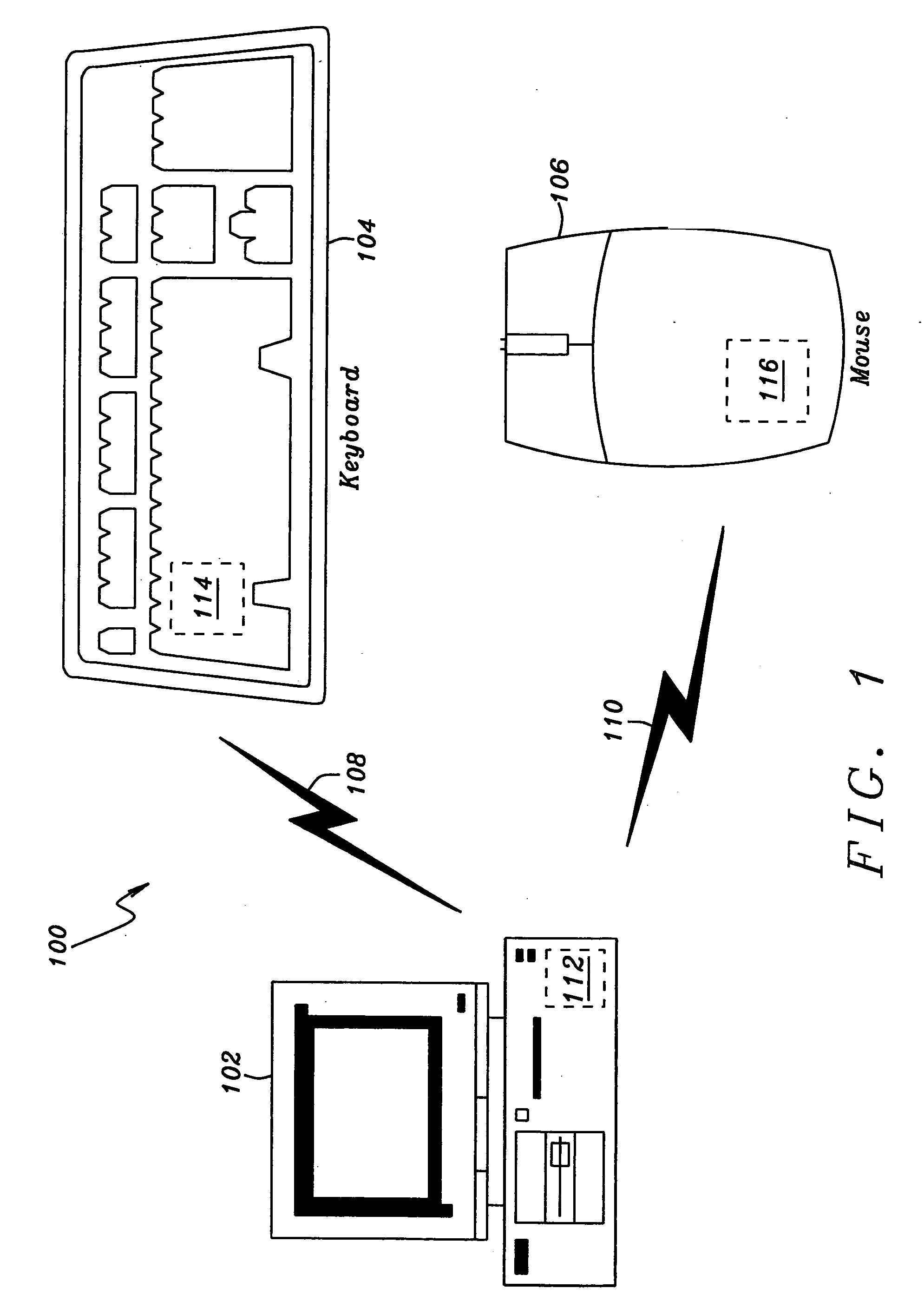
[0054] Referring now to FIG. 1, a first preferred embodiment of the present invention is illustrated. A computer system 100 is shown incorporating a wireless input interface in accordance with the invention includes a host computer 102, a wireless keyboard 104 and a wireless pointing device or “mouse”106. As illustrated in FIG. 1, the wireless keyboard 104 and the wireless mouse 106 are in communication with the host computer 102 over wireless communication links 108 and 110, respectively. As shown, the host computer 102 includes or is attached to a wireless inter...


PUM


Abstract

A wireless interface device for a keyboard of a computer system is achieved. The device comprises a radio transmitter and receiver. A modem encodes data to be sent by the radio transmitter and decodes data received by the radio receiver. A central processing unit is included. A direct signal connection is provided between the wireless interface circuit and a keyboard. A baseband circuit encrypts data to be transmitted and decrypts received data. The wireless interface device has built-in scanning and decoding functions for an input device such as a keyboard or a mouse. The wireless interface device has power saving functions to extend the battery life of the input device. The wireless interface device has the capability of automatically selecting between several communication frequencies or channels. The wireless interface device has the capability of automatically selecting between several data rates.

Description

[0001] This application claims priority to U.S. Provisional Patent Application JAAL-001, “High-Reliability Computer Interface for Wireless Input Device”, Ser. No. 60 / 553,820, filed on Mar. 16, 2004, which is herein incorporated by reference in its entirety. [0002] This application claims priority to U.S. Provisional Patent Application JAAL-002, “Wireless Transceiver System for Computer Input Devices”, Ser. No. 60 / 553,821, filed on Mar. 16, 2004, which is herein incorporated by reference in its entirety. [0003] This application claims priority to U.S. Provisional Patent Application JAAL-003, “Wireless Transceiver System for Computer Input Devices”, Ser. No. 60 / 554,058, filed on Mar. 16, 2004, which is herein incorporated by reference in its entirety. RELATED PATENT APPLICATION [0004] This application is related to U.S. patent application docket number JA05-001, Ser. No. ______, filed on ______, assigned to a common assignee. BACKGROUND OF THE INVENTION [0005] (1) Field of the Inventi...

Claims


Application Information

Patent Timeline
Patent Type & Authority Applications(United States)
IPC IPC(8): G06F1/32G06F3/023G06F3/038G06F13/12G06F13/38G09G5/08H04B7/00H04B7/005H04J1/16H04L5/14H04L9/00H04L9/18
CPCG06F1/3203Y02B60/148G06F1/3237G06F1/3259G06F1/3271G06F3/0231G06F3/03543G06F3/038G06F3/0383G06F13/385G06F2213/3814H04W52/04H04W52/28H04W52/287H04W52/48Y02B60/1217Y02B60/1221Y02B60/1235Y02B60/1253Y02B60/1257Y02B60/50G06F1/3215Y02D10/00
Inventor ANANDAKUMAR, KRISHNASAMYMORRIS, MARTIN GEORGESINGAMSETTY, SURESH KUMARKWAN, DENNIS CHING CHUNGLAW, HOCK THYE
Owner JAALAA
Why Eureka
Try Eureka