Light-emitting apparatus and illuminating apparatus

a technology of light-emitting apparatus and illumination apparatus, which is applied in the direction of light-emitting apparatus, point-like light source, solid-state device, etc., can solve the problems of significantly deteriorating radiation light intensity and brightness in the light-emitting apparatus, and reducing the efficiency of wavelength conversion effected by fluorescent materials, so as to reduce the number of reflections and high radiation light intensity ,

Inactive Publication Date: 2005-10-27
KYOCERA CORP
View PDF5 Cites 42 Cited by
  • Summary
  • Abstract
  • Description
  • Claims
  • Application Information

AI Technical Summary

Benefits of technology

[0015] The invention has been devised in view of the above-described problems with the conventional art, and accordingly its object is to provide a light-emitting apparatus and illuminating apparatus that will succeed in offering high radiation light intensity and high brightness by reducing the number of reflections of light emitted from a light-emitting element occurring on the inner surface of a reflection member and by effectively preventing the light emitted from the light-emitting element from undergoing total reflection at the interface of a fluorescent material layer.

Problems solved by technology

This gives rise to a problem of the radiation light intensity and brightness in the light-emitting apparatus being significantly deteriorated.
As a result, there arises a problem of the radiation light intensity and brightness in the light-emitting apparatus being significantly deteriorated.
As a result, the efficiency of wavelength conversion effected by the fluorescent material is decreased, which leads to a problem of the radiation light intensity and brightness in the light-emitting apparatus being significantly deteriorated.

Method used


Image

  • Light-emitting apparatus and illuminating apparatus
  • Light-emitting apparatus and illuminating apparatus
  • Light-emitting apparatus and illuminating apparatus

Examples


example

[0098] Hereinafter, a description will be given as to an example of the light-emitting apparatus of the invention.

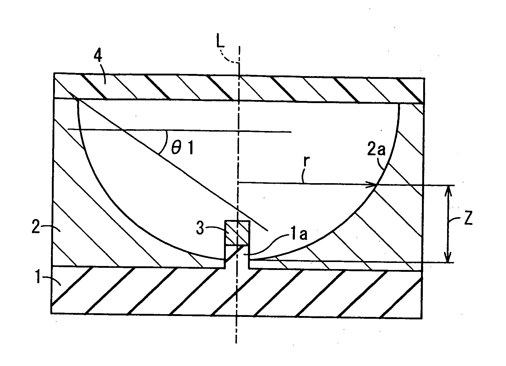
[0099] At first, as the base body 1, an alumina ceramic substrate was prepared. Note that the base body 1 has the convexity 1a formed integrally therewith. The top surface of the convexity 1a is aligned with the top surface of the base body 1 excluding the part in which the convexity la is formed.

[0100] The base body 1 is composed of a rectangular parallelepiped plate which is 8 mm in width×8 mm in depth×0.5 mm in thickness. The base body 1 has, at the center of its top surface, the rectangular-parallelepiped convexity 1a which is 0.35 mm in width×0.35 mm in depth×0.15 mm in thickness.

[0101] In that part of the convexity 1a which carries the light-emitting element 3 was formed a wiring conductor for electrically connecting the light-emitting element 3 to the external electric circuit board through an internal wiring line formed within the base body 1. The wiring condu...


PUM


Abstract

A light-emitting apparatus includes a light-emitting element, a base body, a reflection member and a fluorescent material layer. A cross section of the inner surface of the reflection member cut by a virtual plane including a virtual axis penetrating a center of the inner surface and perpendicular to the upper principal surface of the base body has a sectional profile defined by a curved line expressed by the following formula, and the inner surface of the reflection member is a curved surface obtained by rotating the curved line about the virtual axis: Z=(cr2)/[1+{1−(1+k)c2r2}1/2] (where −10≦k≦−0.001, 0.001≦c≦10). An angle θ1 which is made by an upper surface of the fluorescent material layer and a line which connects one corner of a light-emitting portion of the light emitting element with an uppermost position of the inner surface and is tangent to the one corner, is given as θ1≧90°−sin−1 (1/n1)

Description

BACKGROUND OF THE INVENTION [0001] 1. Field of the Invention [0002] The present invention relates to a light-emitting apparatus housing a light-emitting element, and an illuminating apparatus employing the light-emitting apparatus. [0003] 2. Description of the Related Art [0004]FIG. 4 is a sectional view showing a light-emitting apparatus of conventional design. In FIG. 4, the light-emitting apparatus is mainly composed of a base body 11, a reflection member 12, a light-emitting element 13 and a fluorescent material layer 14. The base body 11 is made of an insulator and has, at the center of its top surface, a placement portion 11a for emplacing thereon the light-emitting element 13. The base body 11 is also provided with a wiring conductor (not shown) formed of, for example, a metallized wiring line and a lead terminal for electrically conductively connecting within and without the light-emitting apparatus through the placement portion 11a and its environs. The reflection member 12...

Claims


Application Information

Patent Timeline
Patent Type & Authority Applications(United States)
IPC IPC(8): F21V7/06F21S4/00F21V7/22F21V9/08F21Y101/02H01L25/075H01L27/15H01L33/50H01L33/60
CPCH01L33/507H01L33/60H01L2924/0002H01L2924/00
Inventor MATSUURA, SHINGO
Owner KYOCERA CORP
Why Eureka
Try Eureka