

Touch panel
a technology of touch panel and controller, applied in the field of touch panel, can solve problems such as burnout of electric components, and achieve the effect of preventing burnout of controllers
- Summary
- Abstract
- Description
- Claims
- Application Information
AI Technical Summary
Benefits of technology
Problems solved by technology
Method used
Image

Examples
Embodiment Construction
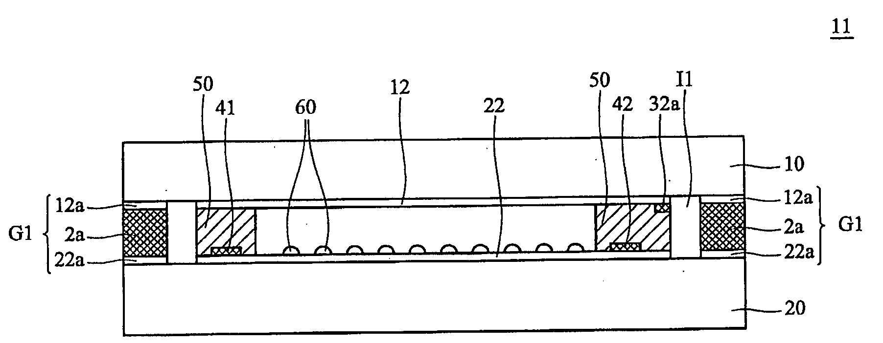
[0019] The following description is of the best-contemplated mode of carrying out the invention. This description is made for the purpose of illustrating the general principles of the invention and should not be taken in a limiting sense. The scope of the invention is best determined by reference to the appended claims.
[0020] It is noted that the description hereinbelow refers to various layers arranged on, above or overlying other layers, to describe the relative positions of the various layers. References to “on”, “above”, “overlying”, or other similar languages, are not limited to the interpretation of one layer being immediately adjacent another layer. There may be intermediate or interposing layers, coatings, or other structures present, and associated process steps present, which are not shown or discussed herein, but could be included to accomplish the intended purpose without departing from the scope and spirit of the invention disclosed herein. Similar, references to struc...
PUM
| Property | Measurement | Unit |
|---|---|---|
| conductive | aaaaa | aaaaa |
| electrical properties | aaaaa | aaaaa |
| area | aaaaa | aaaaa |
Abstract
Description
Claims
Application Information