Apparatus and method for providing a network termination point

Active Publication Date: 2005-10-27
VERIZON PATENT & LICENSING INC
View PDF99 Cites 68 Cited by
  • Summary
  • Abstract
  • Description
  • Claims
  • Application Information

AI Technical Summary

Benefits of technology

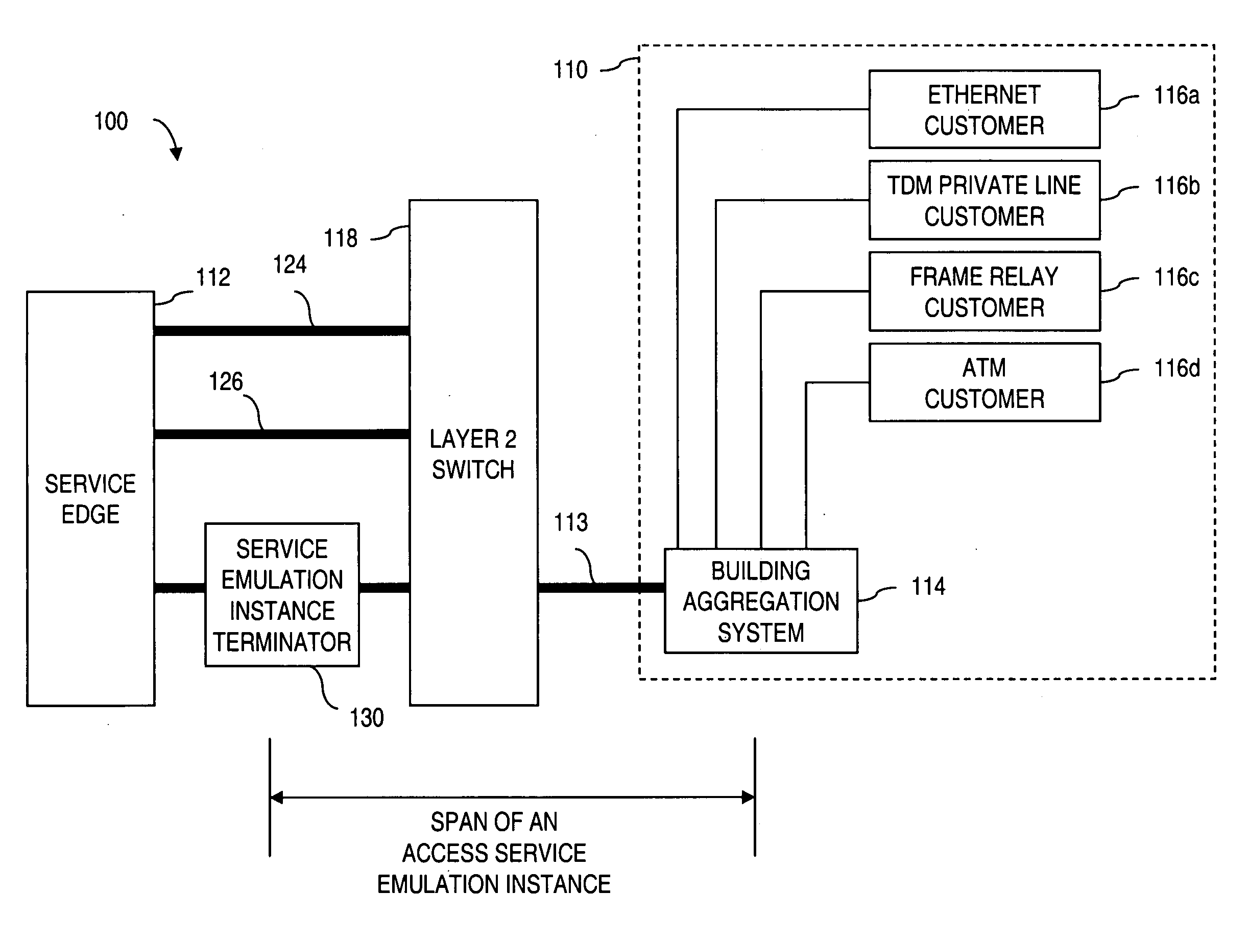
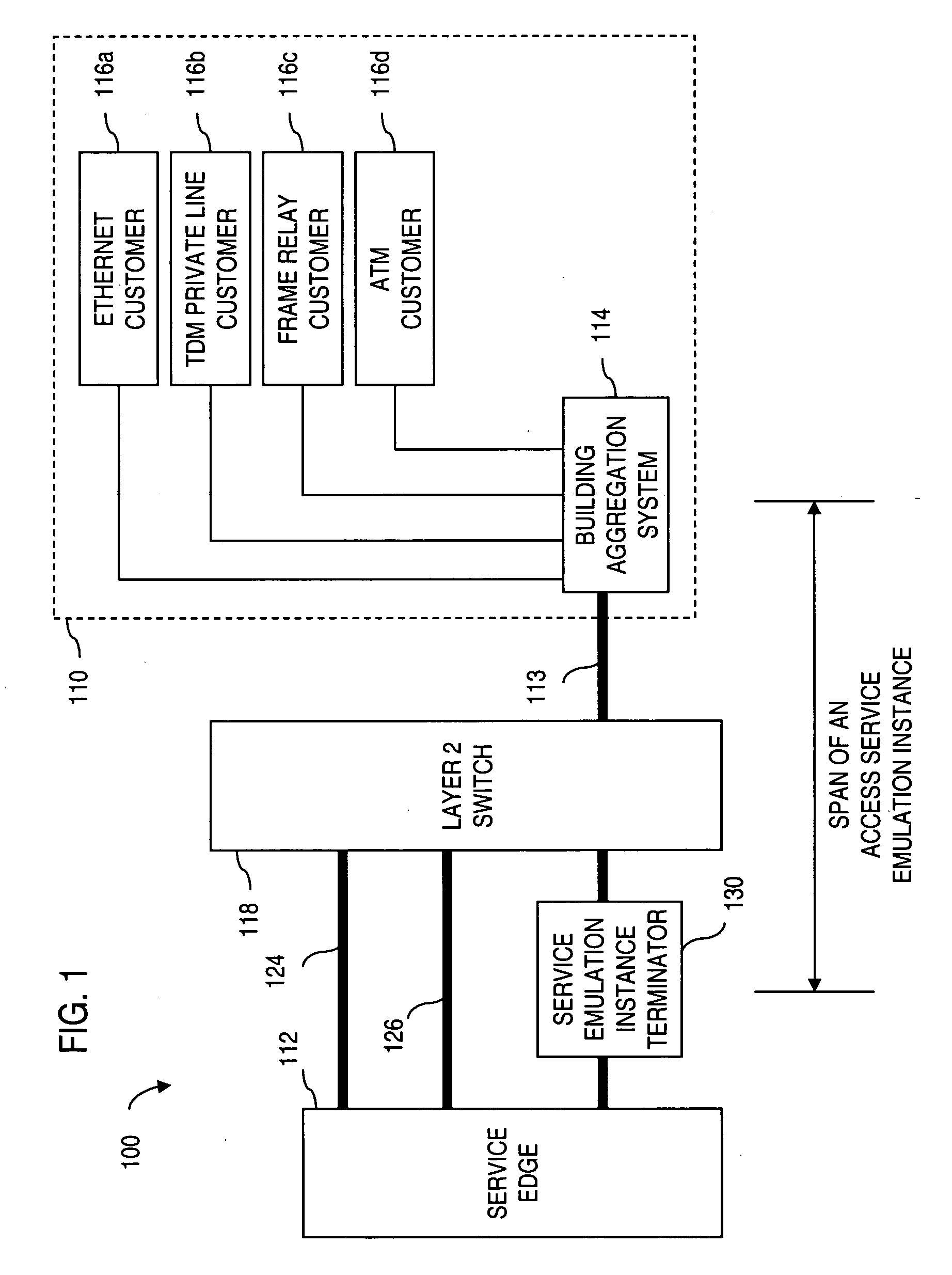
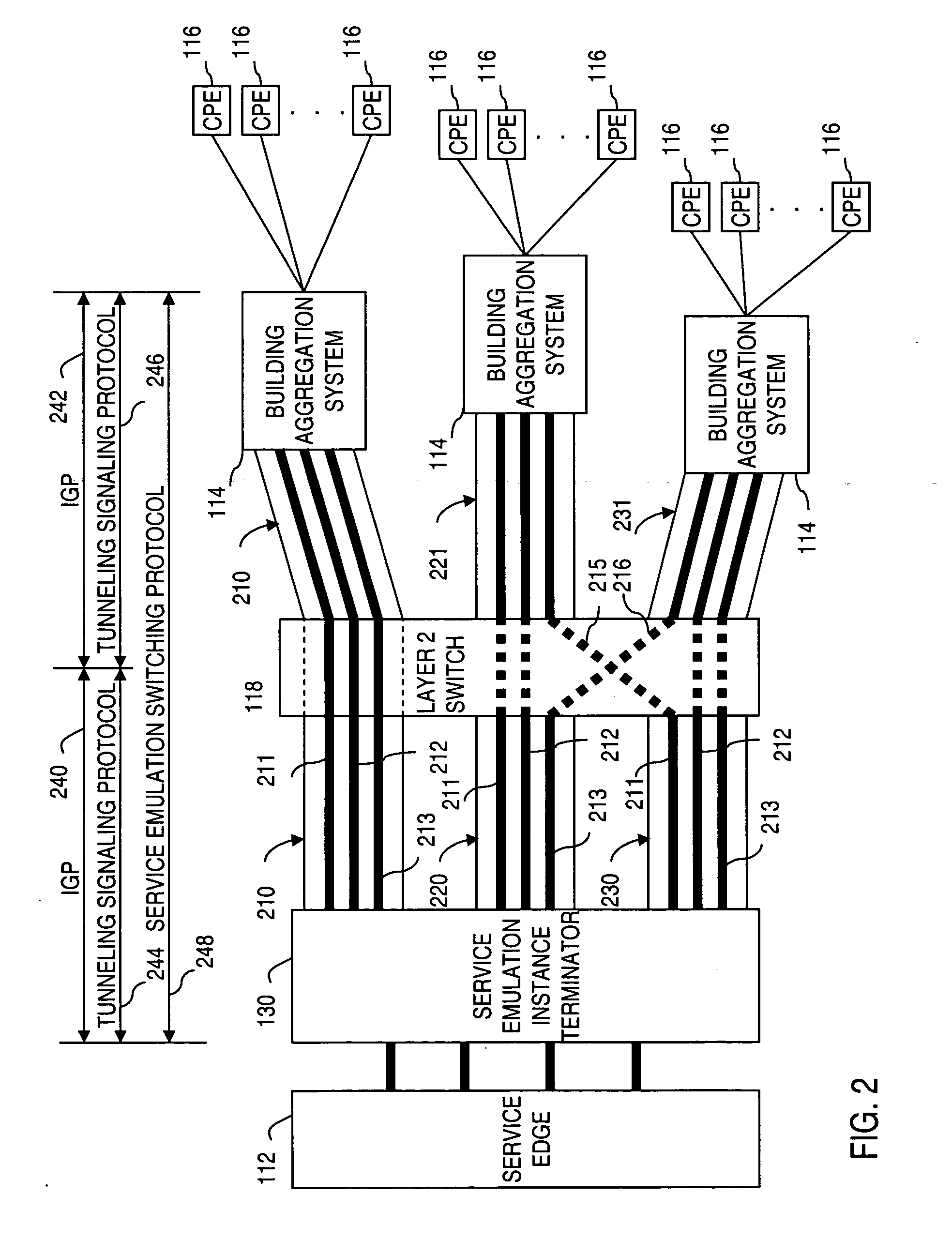
[0007] These and other problems are generally solved or circumvented, and technical advantages are generally achieved, by embodiments of the present invention that provide a termination point for a flow in an access network and functionalities of equipment that may be realized in the termination point. The termination point provides a type of “off-ramp” for aggregated communications that may be sent between a customer site and a provider's service edge, wherein the conversions between various types of transports may be efficiently performed inside the termination point instead of requiring various hardware configurations to be located at several locations. An advantage of such a termination point is that many types of functions may be embedded in the termination point, such as a switching functionality wherein switched traffic may be encapsulated and transmitted over a core network, thus accomplishing the switching functionality in the termination point instead of a hardware switch located elsewhere, thereby affording a provider the capability to provide switching and other functionality in components other than conventional switching devices, such as frame relay switches which may need to be replaced over time.

Problems solved by technology

Further, some types of services, such as frame relay services, may require certain types of switching equipment which may need to be replaced over time.

Method used


Image

  • Apparatus and method for providing a network termination point
  • Apparatus and method for providing a network termination point
  • Apparatus and method for providing a network termination point

Examples


Embodiment Construction

[0023] A system, method, and software for a termination point for a flow in an access network and functionalities of equipment that may be realized in the termination point are described. In the following description, for the purposes of explanation, numerous specific details are set forth in order to provide a thorough understanding of the present invention. It is apparent, however, to one skilled in the art that the present invention may be practiced without these specific details or with an equivalent arrangement. In other instances, well-known structures and devices are shown in block diagram form in order to avoid unnecessarily obscuring the present invention.

[0024] The making and using of the presently preferred embodiments are discussed in detail below. It should be appreciated, however, that the present invention provides many applicable inventive concepts that can be embodied in a wide variety of specific contexts. The specific embodiments discussed herein are merely illus...


PUM


Abstract

Apparatus and method for providing a termination point for service emulation instances in an access network is provided. In an embodiment, the service emulation instances are implemented utilizing, for example, pseudowires. Communications to and from the access network are aggregated and transmitted via one or more pseudowires to a service emulation instance terminator. The service emulation instance terminator converts the traffic to its native form and, if necessary, converts the traffic to a different type of format or service. The service emulation instance terminator then frames the traffic for the appropriate type of service and transmits the traffic to the service edge. Traffic received from the service is removed prepended with a pseudowire label and aggregated with other traffic. The aggregated traffic is transmitted to the customer via the access network. If necessary, an interworking function may convert the traffic from one type of service to another type of service. Further, functionalities of equipment such as frame relay switching or Asynchronous Transfer Mode (ATM) switching may be realized in the service emulation instance terminator.

Description

RELATED APPLICATIONS [0001] The present application is a continuation-in-part of U.S. patent application Ser. No. 10 / 858,491 filed on Jun. 1, 2004, entitled “Apparatus and Method for Terminating Service Emulation Instances,” the contents of which are hereby incorporated by reference.FIELD OF THE INVENTION [0002] The present invention relates generally to a system and method for providing communications services, and more particularly, to a system and method for providing a termination point for a flow in an access network. BACKGROUND OF THE INVENTION [0003] A commercial telecommunications network operated by a service provider supports voice and data communications between customer locations and includes an access network and a core network. Generally, customer devices communicatively couple to the access network, which in turn connects to the core network. The access network includes what many people refer to as “the last mile,” that is, the connectivity from a customer location, s...

Claims


Application Information

Patent Timeline
Patent Type & Authority Applications(United States)
IPC IPC(8): H04L12/28H04L12/46H04L12/56H04L45/02H04L45/50H04M7/00
CPCH04L12/2889H04L12/4633H04L45/10H04M7/006H04L47/10H04L49/602H04L45/50
Inventor DELREGNO, CHRISTOPHER N.
Owner VERIZON PATENT & LICENSING INC
Why Eureka
Try Eureka