

Image forming device
- Summary
- Abstract
- Description
- Claims
- Application Information
AI Technical Summary
Benefits of technology
Problems solved by technology
Method used
Image

Examples
Embodiment Construction
[0030] An image forming device according to preferred embodiments of the present invention will be described while referring to the accompanying drawings wherein like parts and components are designated by the same reference numerals to avoid duplicating description.
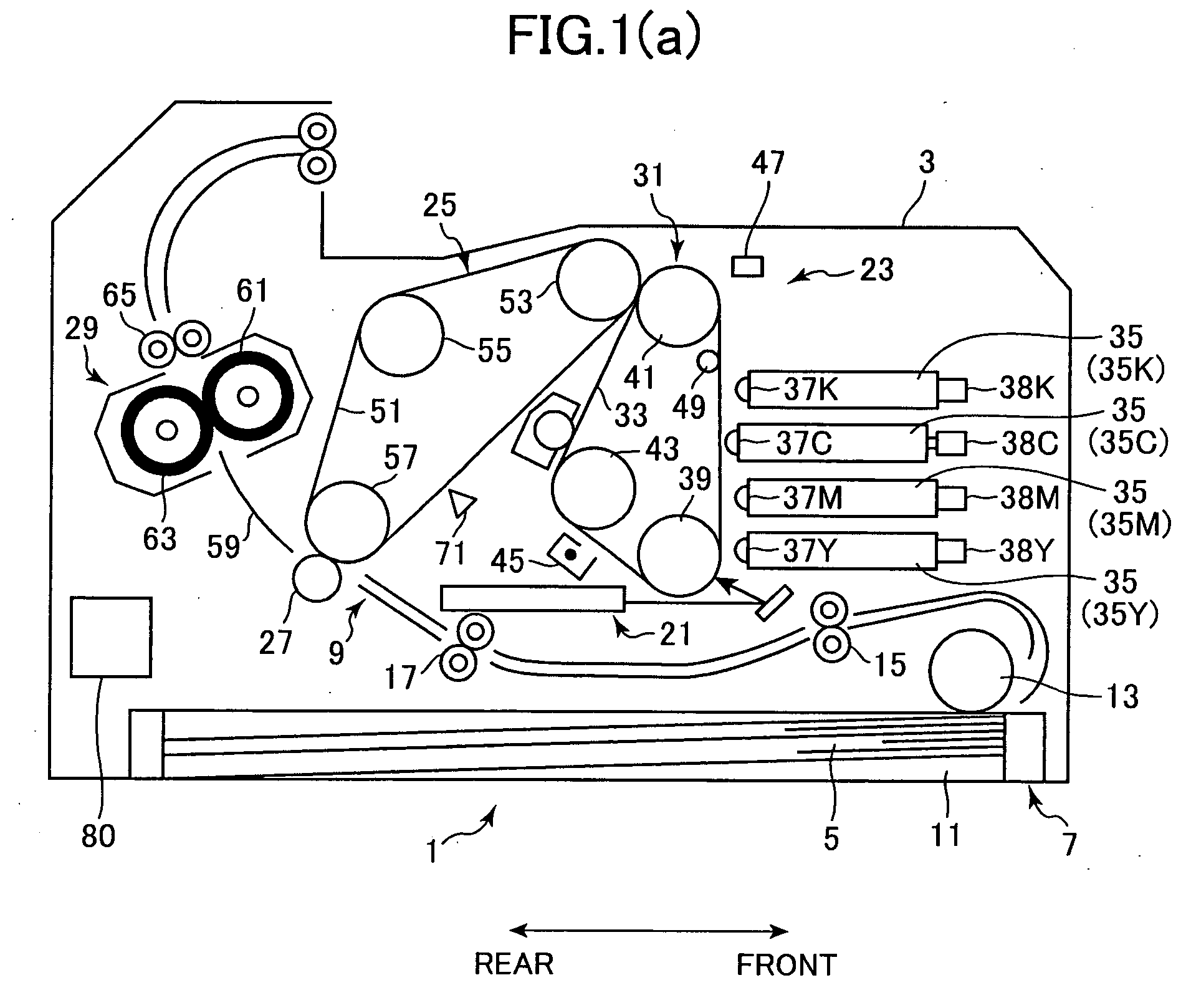
[0031] An image forming device according to the present invention is described below using a four-cycle color laser printer as an example. As shown in FIG. 1(a), the color laser printer 1 has a main case 3 inside of which are a paper supply unit 7 for supplying paper 5, and an image forming unit 9 for forming a specific image on the supplied paper 5.
[0032] The paper supply unit 7 includes a paper tray 11 for storing a stack of paper 5, a supply roller 13 that contacts the top sheet of paper 5 in the paper tray 11 and rotates to supply one sheet at a time to the image forming unit 9, and transportation rollers 15 and registration rollers 17 for conveying the paper 5 to an image formation position.
[0033] The image forma...
PUM
 Abstract
Description
Claims
Application Information