Numerically controlled machine tool

a technology of numerical control and machine tools, applied in the direction of manufacturing tools, metal-working machine components, positioning apparatuses, etc., can solve the problems of inaccurate machined dimensions and the inability to make accurate measurement just by turning the spindle, and achieve the effect of measuring accurately

Inactive Publication Date: 2005-10-27
FANUC LTD
View PDF6 Cites 12 Cited by
  • Summary
  • Abstract
  • Description
  • Claims
  • Application Information

AI Technical Summary

Benefits of technology

[0021] According to the present invention, run-out of the outer surface of the tool holder can be measured accurately without being

Problems solved by technology

Chips caught between a tool holder and a spindle cause a tool holder run-out, resulting in inaccurately machined dimensions.
Therefore, an accurate measurement cannot be made just by turning the spindle, because it

Method used


Image

  • Numerically controlled machine tool
  • Numerically controlled machine tool
  • Numerically controlled machine tool

Examples


Embodiment Construction

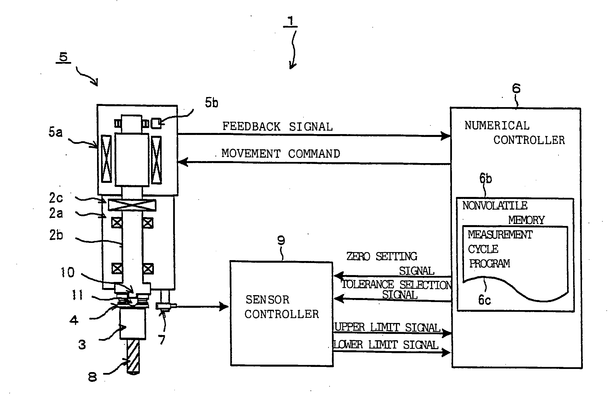
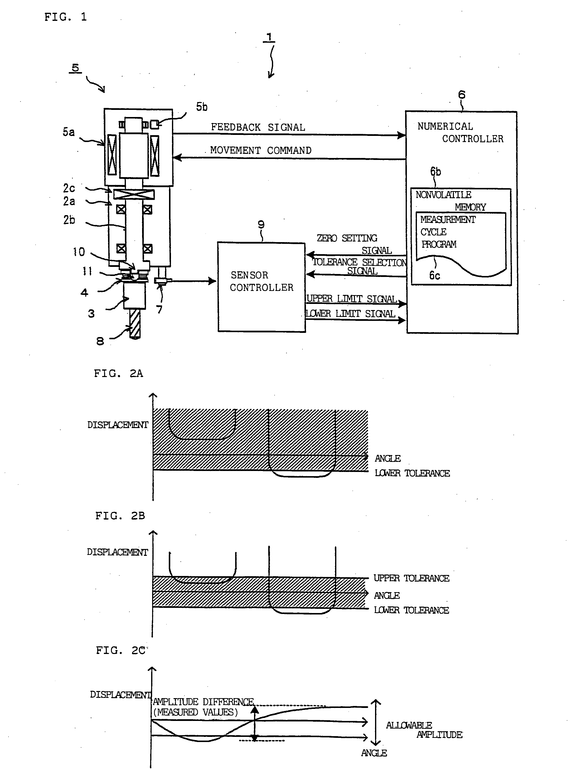
[0041]FIG. 1 schematically illustrates the structure of a numerically controlled machine tool according to the present invention. The numerically controlled machine tool 1 in FIG. 1 comprises a spindle section 2 for rotationally driving a tool 8 and a driving section 5. The driving section 5 is controlled by a numerical controller 6. The numerical controller 6 carries out drive control according to a decision signal from a sensor controller 9 indicating abnormal run-out of the tool holder 3.

[0042] The driving section 5 comprises a spindle motor 5a and a sensor 5b for detecting the rotational state of the spindle motor 5a. The sensor 5b, which may be a magnetic sensor, for example, detects the rotational angle and rotational velocity of the spindle motor 5a.

[0043] The spindle section 2 has a spindle housing 2a, a spindle 2b turned by the spindle motor 5a in the spindle housing 2a, and a coupling 2c for interconnecting the spindle 2b and the spindle motor 5a. The tool holder 3 is mo...


PUM

PropertyMeasurementUnit
Lengthaaaaaaaaaa
Lengthaaaaaaaaaa
Distanceaaaaaaaaaa

Abstract

A numerically controlled machine tool performs machining by rotating a rotational tool attached to a tool holder mounted on a spindle, with keys fitted into key grooves in the tool holder. The numerically controlled machine tool includes predetermined-amount rotating unit for stopping the tool holder at a predetermined rotational position and then rotating the tool holder by a given amount, and a distance sensor which is installed apart from the tool holder and measures a distance to the outer surface of the tool holder. The predetermined-amount rotating unit stops the tool holder at a rotational position at which the key grooves do not face the distance sensor, then rotates the tool holder by the given amount. The distance sensor measures the distance to the tool holder while the tool holder is rotating. The measurement result is compared with a reference distance or distances to discriminate between normal and abnormal rotational run-out of the tool holder.

Description

BACKGROUND OF THE INVENTION [0001] 1. Field of the Invention [0002] The present invention relates to a control function for preventing dimensional error in machining by numerically controlled machine tools equipped with an automatic tool exchanger and, more particularly, to measurement of run-out of the outer surface of a tool holder in order to determine whether the tool has been properly mounted on the spindle of a numerically controlled machine tool. [0003] 2. Description of the Prior Art [0004] machine tools, high machining accuracy, low machining failure rates, and non-delivery of poorly machined products are demanded. For machine tools equipped with an automatic tool exchanger, there is a particularly strong need for detecting chips caught between the tool holder and the spindle during operation of the automatic tool exchanger, to prevent the machining defects that such chips can cause. [0005] Chips caught between a tool holder and a spindle cause a tool holder run-out, result...

Claims


Application Information

Patent Timeline
IPC IPC(8): B23Q3/155B23Q17/22
CPCB23Q17/003B23Q17/22Y10T409/308064Y10T409/30392Y10T409/30728Y10T409/300896
Inventor MUROTA, MASAHIROFUJIMOTO, AKIHIKOWATANABE, NORIO
Owner FANUC LTD
Why Eureka
Try Eureka