Electromagnetically-actuated microfluidic flow regulators and related applications

a flow regulator and microfluidic technology, applied in the direction of piston pumps, positive displacement liquid engines, instruments, etc., can solve the problems of high power consumption, complex automated drug-dosing regimens can be programmed, and high cost of fabrication, so as to optimize the operation and minimize power consumption

Inactive Publication Date: 2005-10-27
CHARLES STARK DRAPER LABORATORY
View PDF98 Cites 161 Cited by
  • Summary
  • Abstract
  • Description
  • Claims
  • Application Information

AI Technical Summary

Benefits of technology

[0010] It is an object of the present invention to provide a flow control system that addresses the disadvantages of known approaches. Specifically, various implementations of the invention generally focus on a variable, closed-loop apparatus for regulating a microfluidic flow that employs a low-power deflection assembly, which is surface-mounted over a flexible membrane overlying a chamber integrated into a microfabricated platform. In various embodiments, to minimize power consumption and optimize the operation, the apparatus relies on magnetic force for deflection of the membrane towards either forward or retracted position thereof.
[0023] In another aspect, the invention stems from the realization that an innovative integrated electrofluidic system can be achieved not by attaching numerous individual fluidic and electronic components on the surface of a common substrate and then interconnecting the components with microtubules, but instead by utilizing a commercially available, Low-cost polymer material with a thin layer of adhesive which is machined and processed to define microfluidic and / or electronic components directly on the polymer material; additional layers of the polymer / adhesive material are added and additional microfluidic and / or electronic components may be defined; the layers are then laminated with the thin layer of adhesive which efficiently seals and bonds the layers. As a result, the microfluidic and / or electronic components are embedded within the system.

Problems solved by technology

In addition, complex automated drug-dosing regimens can be programmed into the system or even implemented to respond to sensor input of physiological measurements.
Drawbacks of these known approaches, however, include high cost of fabrication, dependence on specific properties of the fluid to be controlled, high power consumption, and unreliable performance over a range of pressures, as well as limited control functionality.
These prior-art approaches suffer from several distinct disadvantages.
Interconnecting the individual microfluidic and electronic components with delicate microtubules can be time consuming, expensive, and unreliable.
This, in turn, increases the total system volume of fluid and, therefore, increases the size of the samples required for analysis.
Increased fluid volume also results in a decrease in performance due to longer system response time, and also decreases the functionality and reliability of the microsystem.
The requirement of multiple placement steps to position the microfluidic and electronic components on the substrate and using discrete wires to interconnect the various components complicates the manufacturing processes, decreases reliability, and increases costs.
Moreover, silicon and glass materials are more expensive than other readily available materials, such as polymers.

Method used


Image

  • Electromagnetically-actuated microfluidic flow regulators and related applications
  • Electromagnetically-actuated microfluidic flow regulators and related applications
  • Electromagnetically-actuated microfluidic flow regulators and related applications

Examples


Embodiment Construction

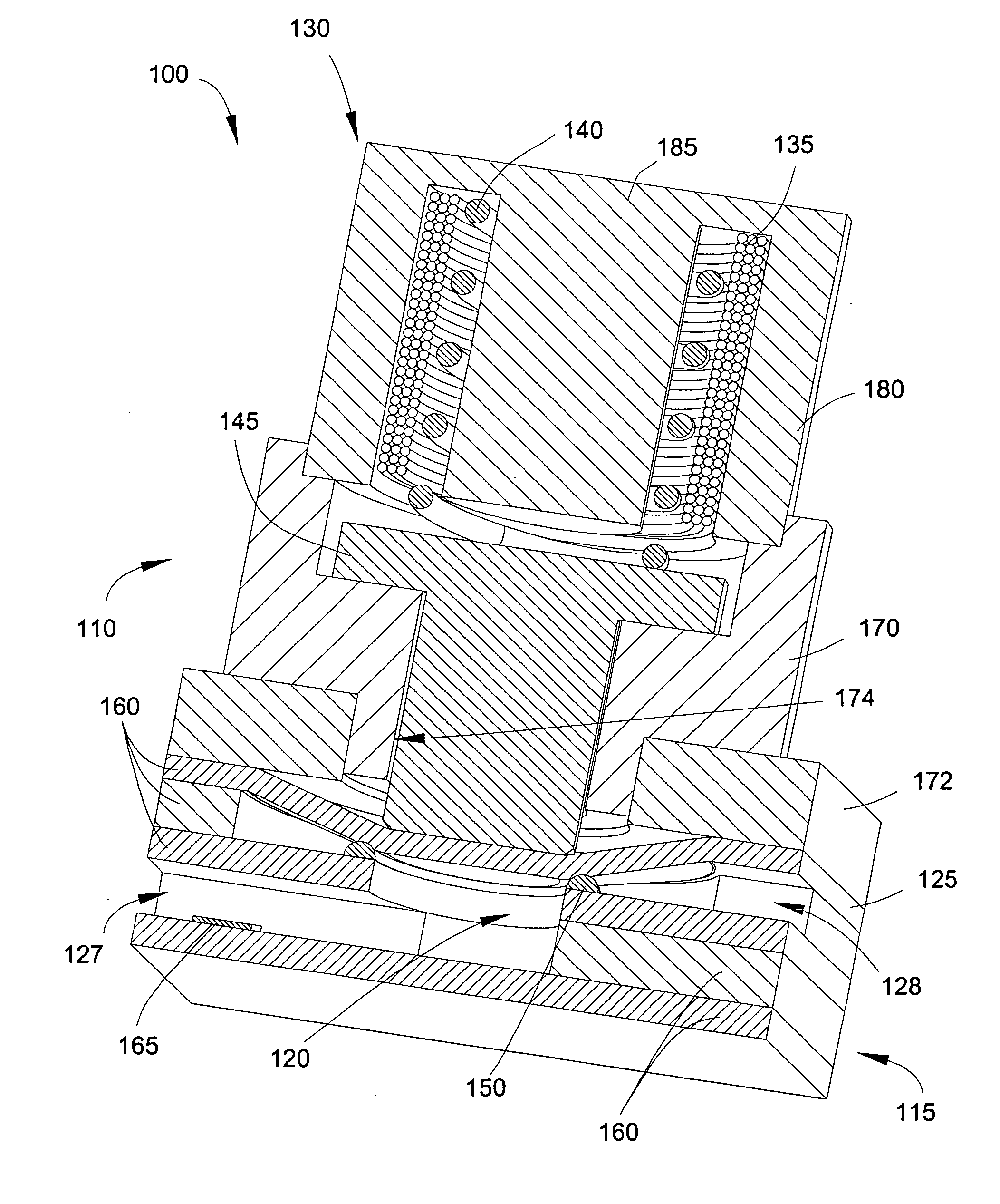
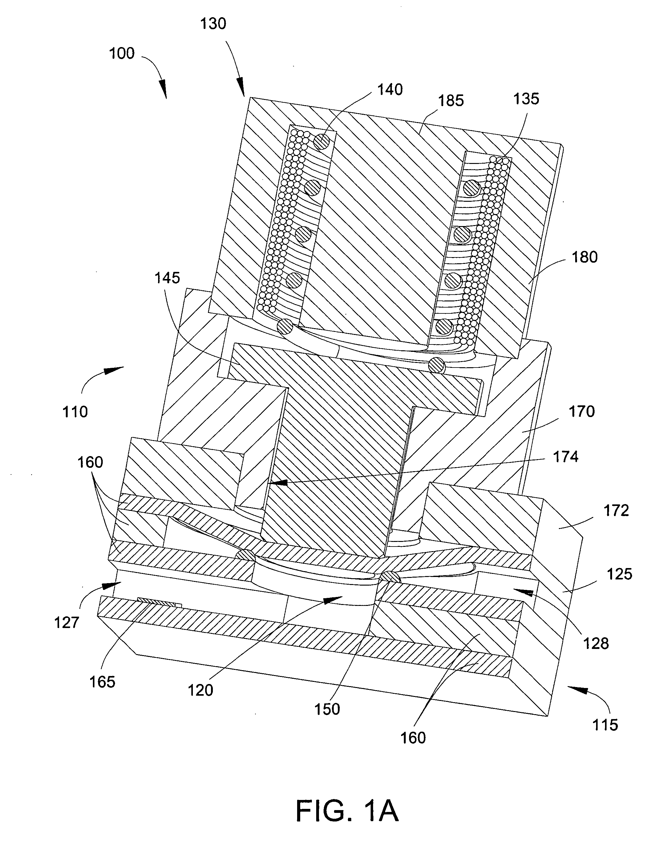
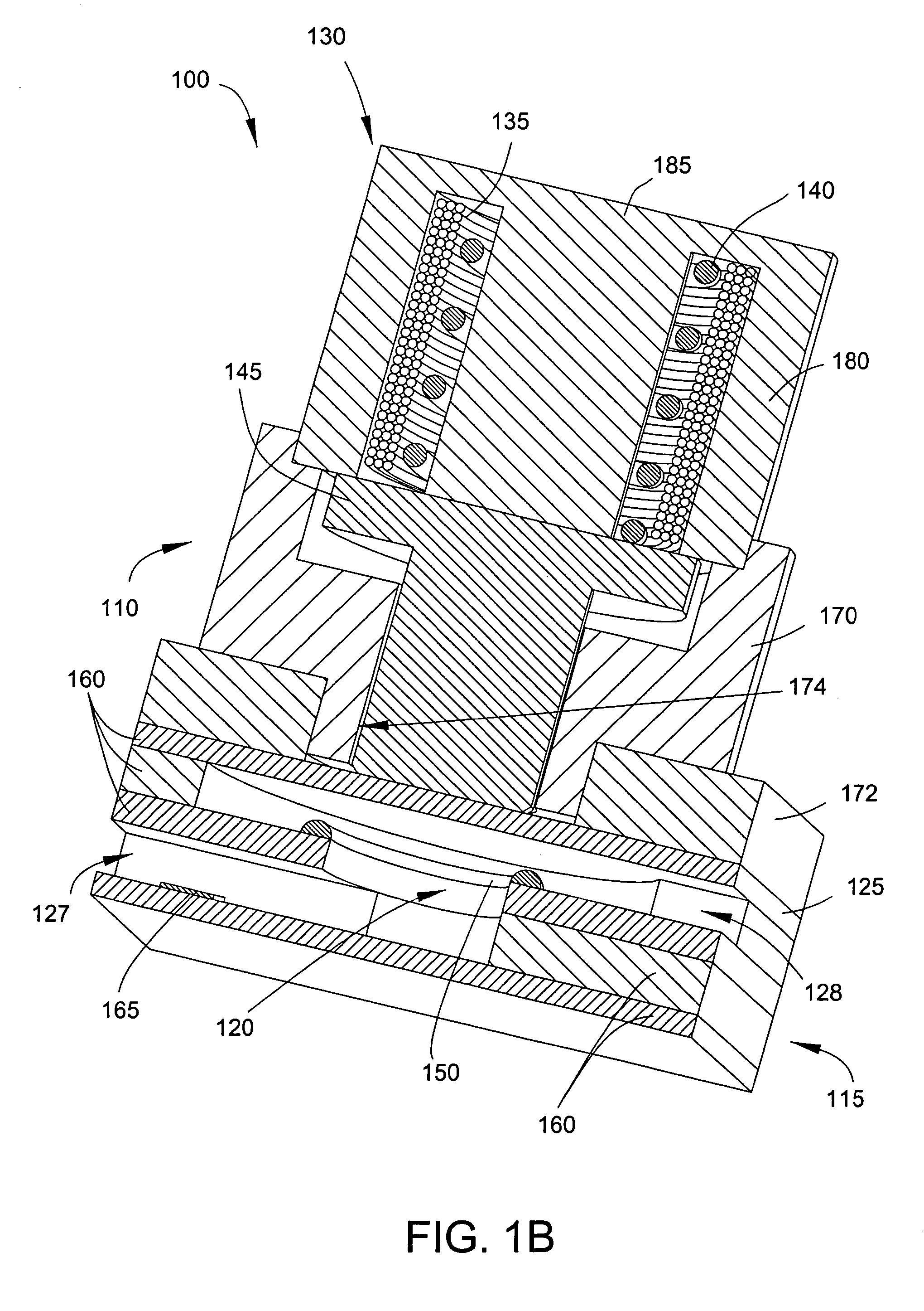
[0045] As mentioned above, various aspects of the invention contemplate a variable, closed-loop apparatus for regulating a microfluidic flow employing a tow-power deflection assembly, which is surface-mounted over a flexible membrane that overlies a chamber integrated into a substrate, thereby allowing for modular flexibility and rapid prototyping. In various embodiments, to minimize power consumption and optimize the operation, the apparatus relies on magnetic force for deflection of the membrane towards either forward or retracted position thereof. White generally described in conjunction with a microfabricated substrate, various aspects of the invention may employ a substrate fabricated using known precision non-microscale methods of manufacturing printed circuit boards.

[0046] Referring to FIGS. 1A-1B, in various embodiments, an apparatus 100 for regulating a microfluidic flow includes an electromagnetically-driven assembly 110 fabricated by conventional machining techniques and...


PUM


Abstract

A variable, closed-loop apparatus for regulating a microfluidic flow that employs a low-power deflection assembly, which is surface-mounted over a flexible membrane overlying a chamber integrated into a microfabricated platform. A flexible membrane, moveable between two positions, sealingly overlies the chamber. One of the positions of the membrane restricts the flow through the chamber to a greater degree than the other position. A deflection assembly disposed on the substrate over the membrane unidirectionally deflects the membrane, thereby regulating the flow through the chamber.

Description

CROSS-REFERENCE TO RELATED APPLICATIONS [0001] This application is a continuation-in-part of U.S. patent application Ser. No. 11 / 046,540, filed Jan. 28, 2005, which claims priority to and the benefit of U.S. provisional application Ser. No. 60 / 540,283, filed Jan. 29, 2004, and U.S. provisional application Ser. No. 60 / 602,691, filed Aug. 19, 2004. This application is also a continuation-in-part of U.S. patent application Ser. No. 10 / 601,606, filed Jun. 23, 2003, which claims priority to and the benefit of U.S. provisional application Ser. No. 60 / 390,773, filed Jun. 21, 2002. Disclosures of all of these applications are incorporated herein by reference in their entireties.FIELD OF THE INVENTION [0002] The present invention relates generally to the field of flow control systems, and, more particularly, to electromagnetically-actuated microfluidic flow regulators mounted over substrates for manipulating small quantities of fluids at low flow rates. BACKGROUND OF THE INVENTION [0003] Eme...

Claims


Application Information

Patent Timeline
Patent Type & Authority Applications(United States)
IPC IPC(8): F04B17/00F04B35/04F04B43/04
CPCA61M5/14224A61M5/14276A61M2205/0244A61M2210/0662G05D7/0694F04B35/045F04B43/043F04B43/046A61M2210/0668F04B43/14
Inventor MESCHER, MARK J.FIERING, JASON O.DUBE, CHRISTOPHER
Owner CHARLES STARK DRAPER LABORATORY
Why Eureka
Try Eureka