Method and apparatus for adjustable hot runner assembly seals and tip height using active material elements

a technology of active material elements and hot runner, which is applied in the direction of dough shaping, manufacturing tools, food shaping, etc., can solve the problems of passive devices relatively incapable of being actively controlled or capable of different levels of performance, and achieve the effect of effective and efficien

Inactive Publication Date: 2005-10-27
HUSKY INJECTION MOLDING SYST LTD
View PDF22 Cites 30 Cited by
  • Summary
  • Abstract
  • Description
  • Claims
  • Application Information

AI Technical Summary

Benefits of technology

[0008] It is an advantage of the present invention to provide injection molding machine apparatus and methods to overcome the problems noted above, and to advantageously provide an effective, efficient means for adjusting nozzle tip height and hot runner seals in an injection molding machine.
[0009] According to a first aspect of the present invention, structure and/or steps are provided for sealing a first surface and a second surface in an injection mold, including an active material actuator disposed to move the first surface toward the second surface, and transmission structure configured to transmit electricity, in use, to said active material actuator, to cause said active material actuator to seal the first surface and the second surface.
[0010] According to a second aspect of the present invention, structure and/or steps are provided for moving the nozzle tip of an injection mold hot runner nozzle with respect to a mold gate, including an active material actuator configured to move the nozzle tip with respect to the mold gate, and transmission structure con

Problems solved by technology

These sealing structures suffer from being passive devices relatively incapab

Method used


Image

  • Method and apparatus for adjustable hot runner assembly seals and tip height using active material elements
  • Method and apparatus for adjustable hot runner assembly seals and tip height using active material elements
  • Method and apparatus for adjustable hot runner assembly seals and tip height using active material elements

Examples


first embodiment

2. The Structure of the First Embodiment

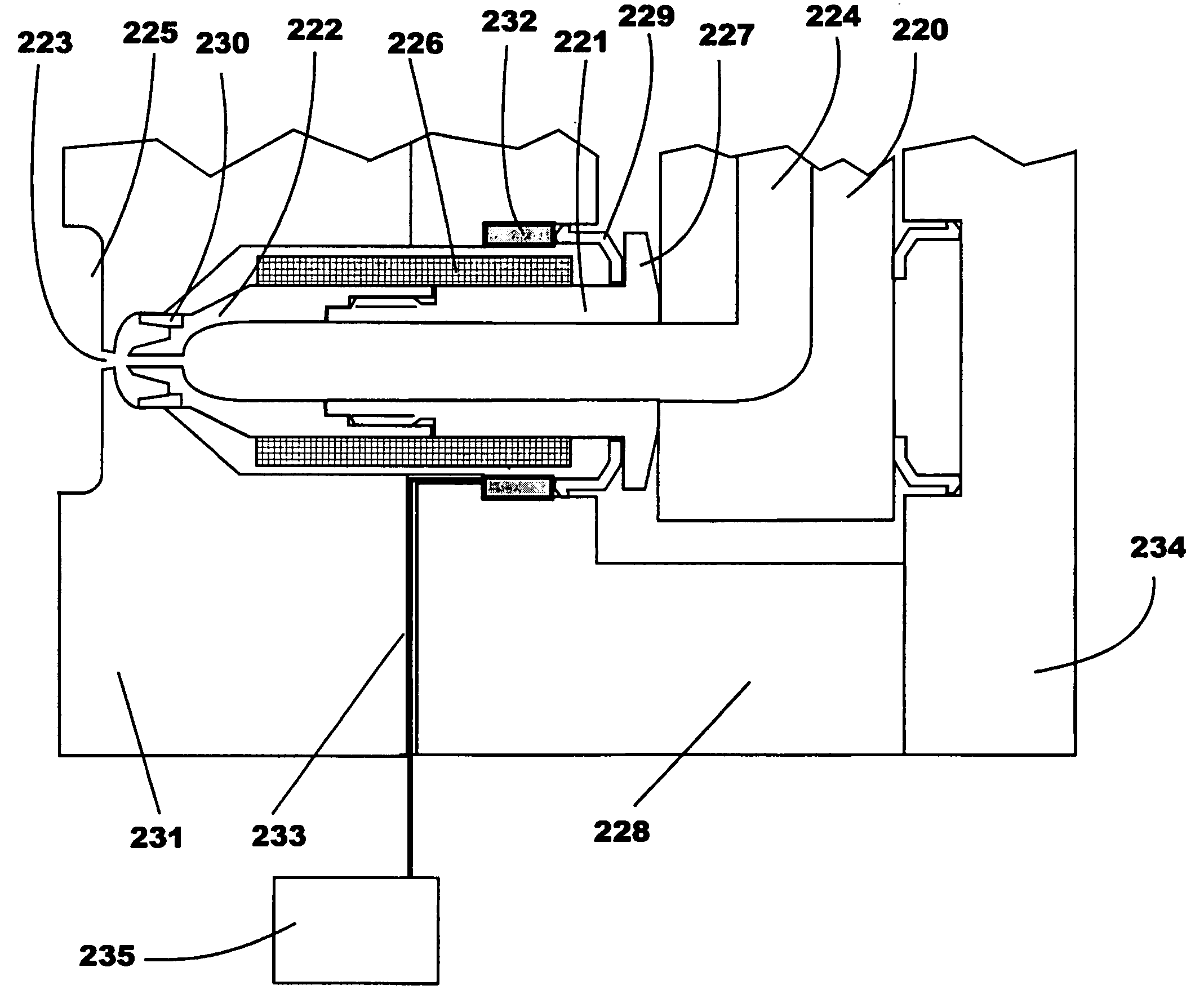
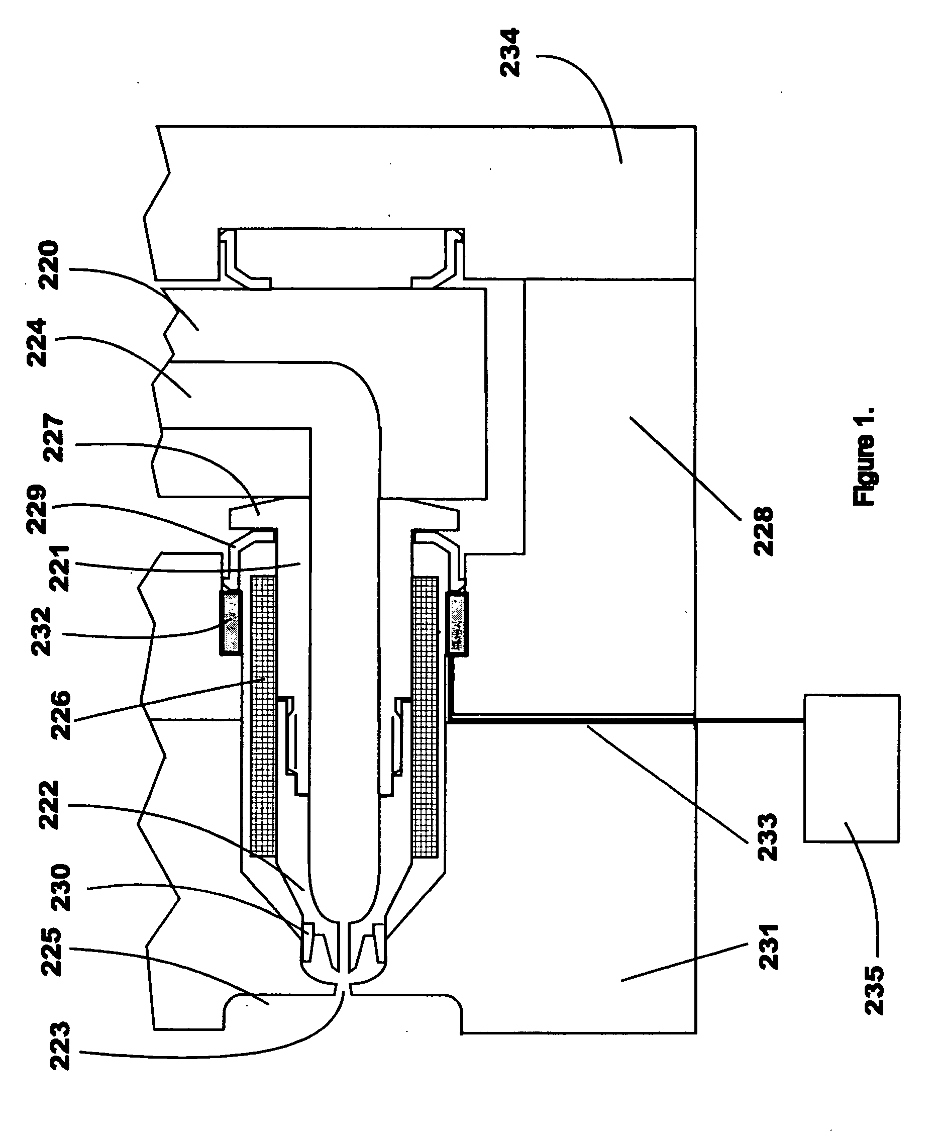
[0019] The first preferred embodiment of the present invention is shown in FIG. 1, which depicts a hot runner nozzle assembly including a hot runner manifold 220, a manifold backing plate 234, a hot runner nozzle body 221, tip 222 and gate 223. Melt channel 224 conveys molten resin through the manifold, nozzle and gate to the mold cavity 225. The nozzle is heated by heater 226 that, in addition to maintaining the molten state of the resin as it flows through the nozzle, also causes the nozzle body to increase in length and diameter due to thermal expansion.

[0020] The nozzle body 221 has a head 227 that is pressed against the manifold 220 to ensure that a seal is effected at the connection of the two surfaces, so that resin passing through the melt channel 224 does not leak at the interface when subjected to injection pressure. The nozzle body 221 is typically positioned within the manifold plate 228 by nozzle insulator 229, and positioned wit...

second embodiment

4. The Structure of the Second Embodiment

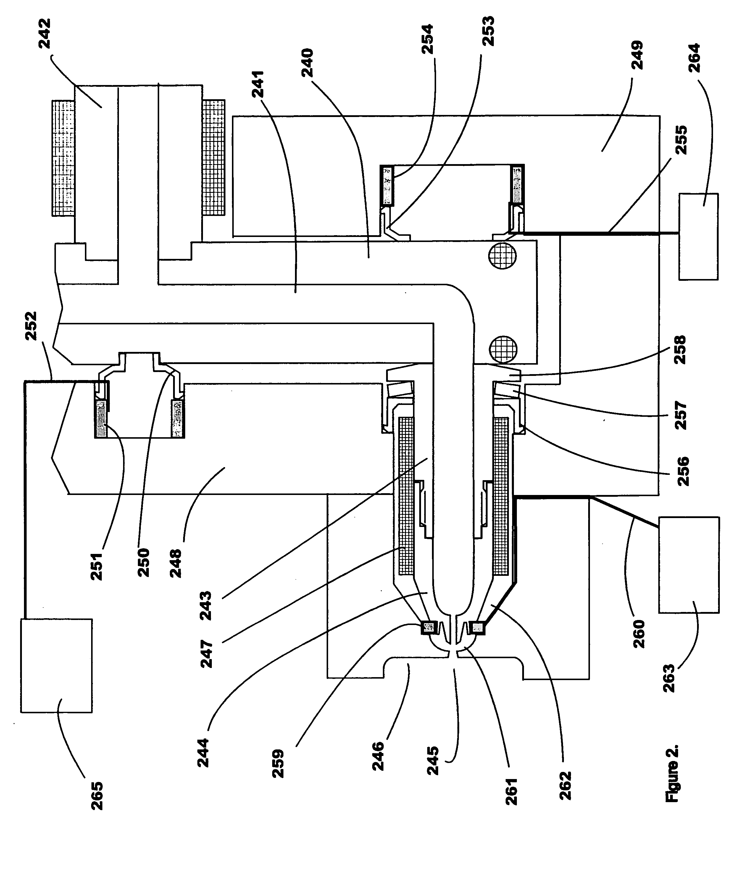
[0029]FIG. 2 shows a second embodiment according to the present invention in which a hot runner assembly comprising a sprue bushing 242 is attached to a manifold 240 containing a melt channel 241 that connects to a nozzle housing 243 having a nozzle tip 244 threaded onto its end. The manifold 240 is spaced from the manifold plate 248 by center insulator 250 and nozzle housing insulator 256, and from the manifold backing plate 249 by backup insulator 253, such that heat losses from the manifold to the cooled mold plates are minimized.

[0030] The head of the nozzle housing 258 is constantly urged against the manifold 240 by spring washer 257 so that a seal is maintained at the interface of the two components so that pressurized melt flowing through channel 241 to the nozzle tip 244 and through the gate 245 to fill mold cavity 246 will not leak. The nozzle housing heater 247 keeps the housing at operating temperature, thereby allowing the melt t...

third embodiment

6. The Structure of the Third Embodiment

[0037]FIG. 3 shows a third preferred embodiment in accordance with the present invention, in which a hot runner assembly includes a manifold 282 containing a melt channel 283 that connects to a nozzle housing 281. A nozzle tip 275 is threaded onto the end of the nozzle housing 281. The manifold 282 is spaced from the manifold backing plate 286 by backup insulator 284 and spring washer 285, and is also spaced from the manifold plate 287 by the nozzle housing insulator 279 and spring washer 280, such that heat losses from the manifold to the cooled mold plates are minimized. The head of the nozzle housing 281 is constantly urged against the manifold 282 by spring washer 280 so that a seal is maintained at the interface of the two components so that pressurized melt flowing through channel 283 to the nozzle tip 275 and through the gate 270 to fill mold cavity 271 will not leak. The nozzle housing heater 276 keeps the housing at operating temperat...


PUM

PropertyMeasurementUnit
Forceaaaaaaaaaa
Pressureaaaaaaaaaa
Electric potential / voltageaaaaaaaaaa

Abstract

Method and apparatus are provided for sealing interfaces within an injection mold having a first surface and a second surface includes an active material actuator configured to be disposed in a manner suitable for generating a force between the first surface and the second surface. The active material actuator is configured to generate a force in response to sense signals from a transmission structure. Methods and apparatus are also provided for centering a nozzle tip within a gate opening, and adjusting tip height of a nozzle tip with respect to a gate opening, also using active material inserts.

Description

BACKGROUND OF THE INVENTION [0001] 1. Field of the Invention [0002] The present invention relates to a method and apparatus for providing adjustable hot runner assembly seals, as well as adjustable hot runner nozzle tip height, by utilizing active material elements in injection molding machine equipment (e.g., hot runner nozzle assemblies). “Active materials” are a family of shape altering materials such as piezoactuators, piezoceramics, electrostrictors, magnetostrictors, shape memory alloys, and the like. In the present invention, they are used to adjust the hot runner assembly seals and to adjust the nozzle tip height, thereby improving the quality of the molded article, the life of the nozzle assembly, and the resin sealing. The active material elements may also be used as sensors. [0003] 2. Related Art [0004] Active materials are characterized as transducers that can convert one form of energy to another. For example, a piezoactuator (or motor) converts input electrical energy ...

Claims


Application Information

Patent Timeline
IPC IPC(8): B29C45/20B29C45/26B29C45/27B29C45/28B29C45/77
CPCB29C45/2608B29C45/2701B29C2045/2722B29C2045/2761B29C2045/2796B29C2945/76277B29C2945/76381B29C2945/76755B29C2945/76458B29C2945/76006B29C2945/76518B29C45/28B29C45/77B29C45/20
Inventor JENKO, EDWARD J.
Owner HUSKY INJECTION MOLDING SYST LTD
Why Eureka
Try Eureka