Fuel cell stack defrosting
- Summary
- Abstract
- Description
- Claims
- Application Information
AI Technical Summary
Benefits of technology
Problems solved by technology
Method used
Image
Examples
second embodiment
[0083] Next, referring to FIG. 6 and FIGS. 7A, 7B, this invention will be described.
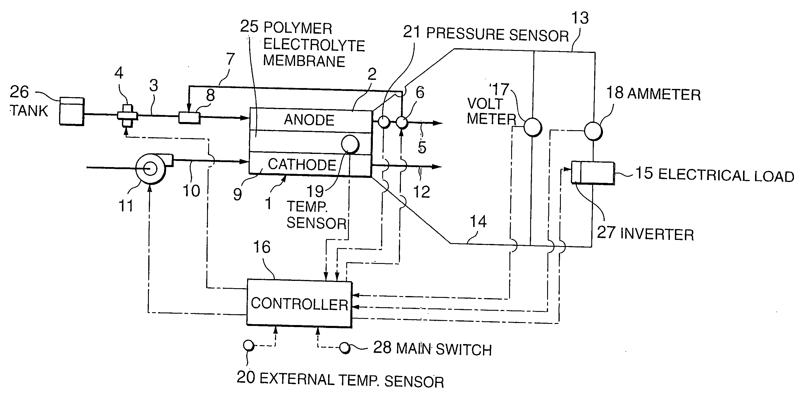
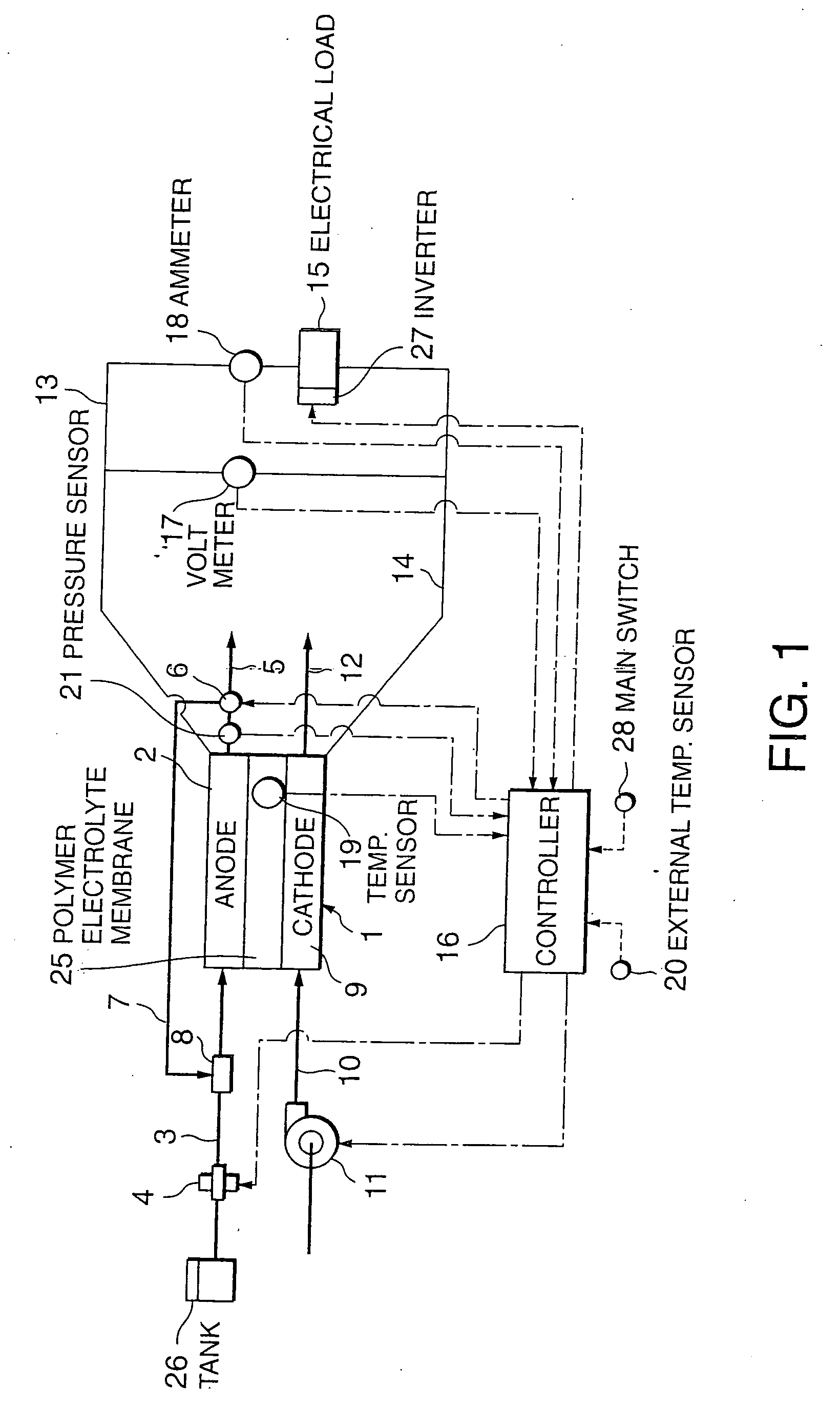
[0084] The fuel cell power plant according to this embodiment has an identical hardware constitution to that of the first embodiment, but the logic for controlling the pulse-form output current is different to the first embodiment.
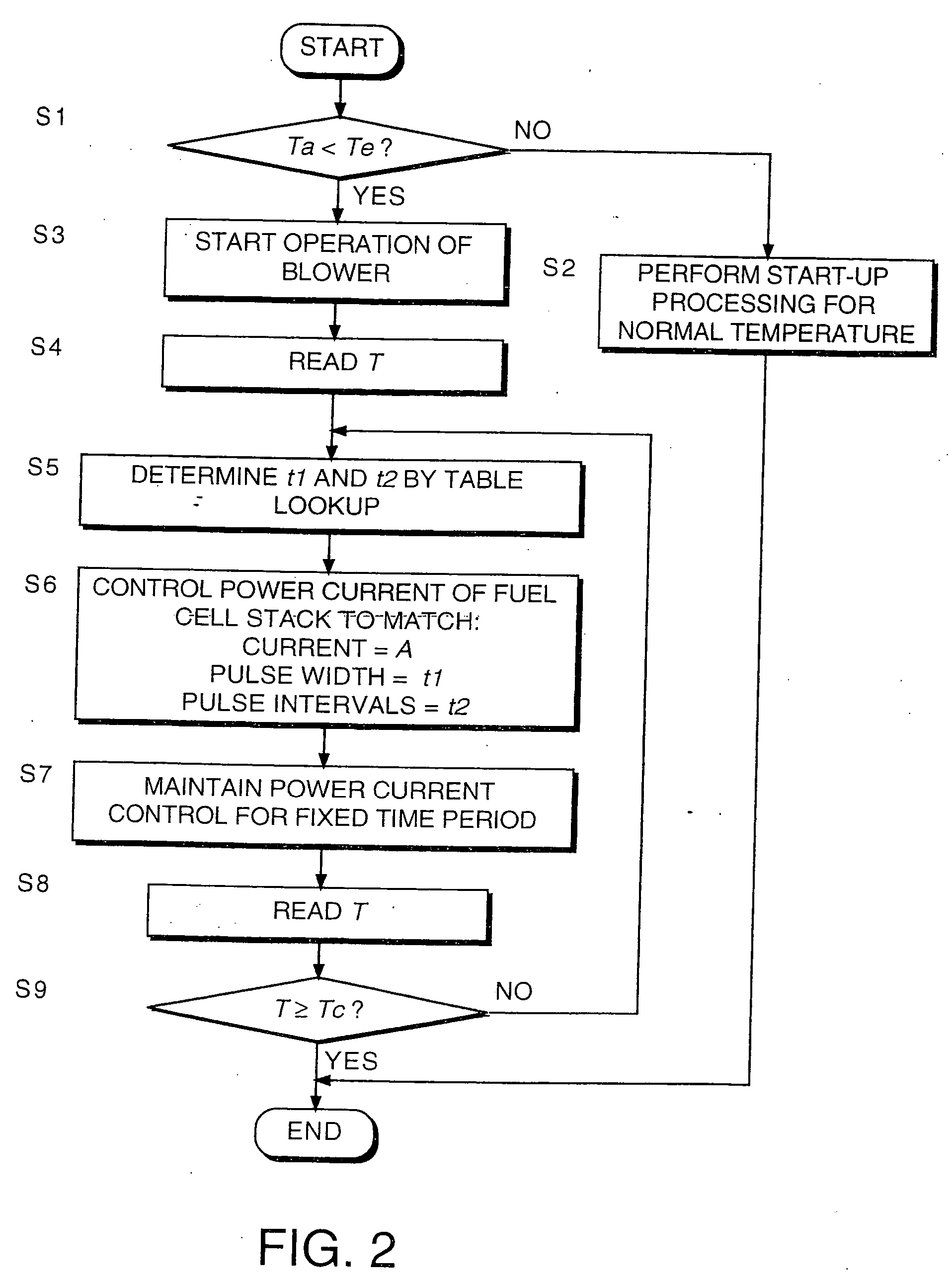
[0085] In this embodiment, the controller 16 executes a defrosting routine shown in FIG. 6 in place of the defrosting routine shown in FIG. 2.
[0086] The processing in steps S1-S3 and steps S8, S9 is identical to the defrosting routine of FIG. 2.
[0087] After beginning operation of the blower 11 in the step S3, the controller 16 controls the inverter 27 in a step S21 to begin power generation in the fuel cell stack 1 under the output current A.
[0088] Next, in a step S22, the controller 16 reads the terminal voltage V of the fuel cell stack 1 which is detected by the voltmeter 17.
[0089] Next, in a step S23, the controller 16 compares the terminal voltage V with the preset...
first embodiment
[0090] Then, similarly to the defrosting routine in FIG. 2, a determination is made in the steps S8 and S9 as to whether or not the temperature T of the fuel cell stack 1 has reached a temperature Tc at which normal operations are possible. The processing of the step S21 onwards is repeated until the temperature T reaches the normal operating temperature Tc, and when the temperature T reaches the normal operating temperature Tc, the routine ends. Control of the air supply to the cathode 9 is performed in a similar manner to the
[0091] Variation in the output current and terminal voltage under the control according to this embodiment is illustrated in FIGS. 7A and 7B. As shown in FIG. 7A, the terminal voltage V of the fuel cell stack 1 declines rapidly as a result of outputting a pulse current corresponding to the output current A, but when moisture accumulates in the gas passage and gas diffusion layer such that the air supply to the cathode 9 is blocked, the terminal voltage V decli...
third embodiment
[0095] Next, referring to FIGS. 8 and 9, this invention will be described.
[0096] The hardware constitution of the fuel cell power plant in this embodiment is identical to that of the first embodiment, and only the method for setting the pulse width t1 and pulse interval t2 differs from the first embodiment. More specifically, the controller 16 executes a defrosting routine shown in FIG. 8 in place of the defrosting routine in FIG. 2.
[0097] Referring to FIG. 8, in this routine steps S31 and S32 are provided in place of the steps S4 and S5 of the defrosting routine in FIG. 2. All other steps are identical to those in the routine in FIG. 2. The controller 16 is installed with a timer for counting elapsed time after the main switch is switched on by the driver. The elapsed time after the main switch is switched on is equal to the elapsed time following the beginning of defrosting of the fuel cell stack 1.
[0098] In the step S31, the controller 16 reads the elapsed time t0 after the mai...
PUM
 Abstract
Description
Claims
Application Information
 - R&D
- Intellectual Property
- Life Sciences
- Materials
- Tech Scout
- Unparalleled Data Quality
- Higher Quality Content
- 60% Fewer Hallucinations
Browse by: Latest US Patents, China's latest patents, Technical Efficacy Thesaurus, Application Domain, Technology Topic, Popular Technical Reports.
© 2025 PatSnap. All rights reserved.Legal|Privacy policy|Modern Slavery Act Transparency Statement|Sitemap|About US| Contact US: help@patsnap.com


