Capacity control valve

Active Publication Date: 2020-01-30
EAGLE INDS
View PDF0 Cites 9 Cited by
  • Summary
  • Abstract
  • Description
  • Claims
  • Application Information

AI Technical Summary

Benefits of technology

[0014]In order to address the problem with the conventional art described above, the present invention provides a capacity control valve having an auxiliary communication passage to be improved in the function for discharging a liquefied refrigerant from a contro

Problems solved by technology

As long as the liquefied refrigerant is not discharged, the refrigerant gas cannot be compressed when the compressor is restarted, and the pre-set discharge rate cannot

Method used


Image

  • Capacity control valve
  • Capacity control valve
  • Capacity control valve

Examples


Example

First Embodiment

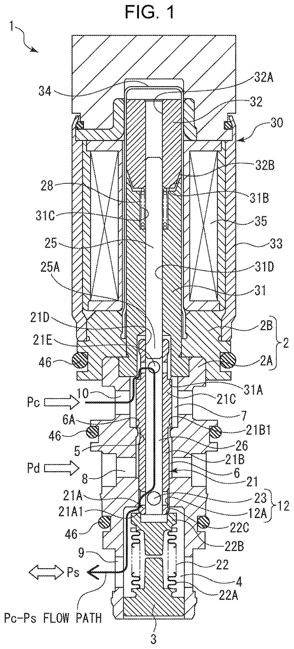
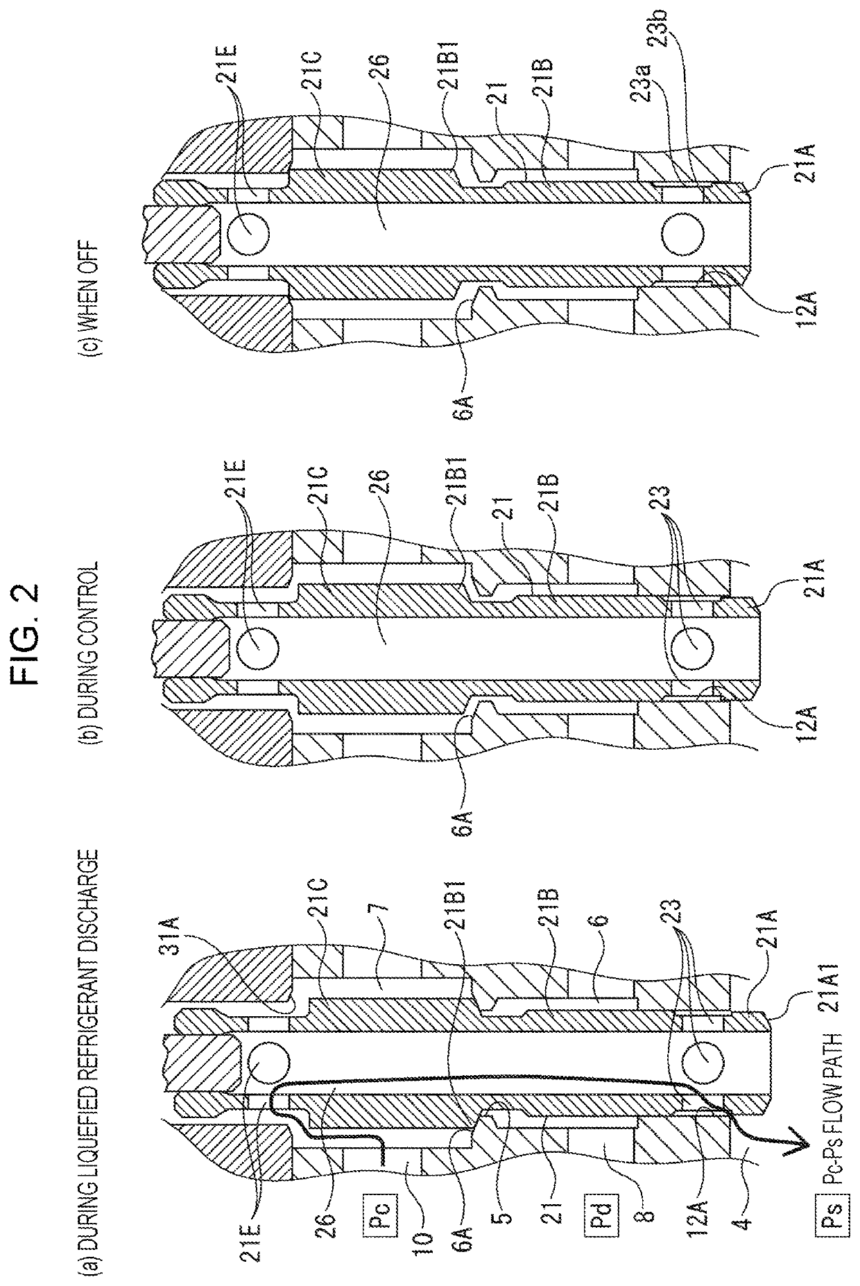
[0056]A capacity control valve according to a first embodiment of the present invention will be explained with reference to FIGS. 1 to 3. In FIG. 1, the reference numeral 1 refers to the capacity control valve. The capacity control valve 1 mainly includes a valve body 2, a valve element 21, a pressure-sensitive element 22, and a solenoid portion 30. Hereinafter, the components of the capacity control valve 1 will be explained individually.

[0057]The valve body 2 includes a first valve body 2A and a second valve body 2B, the first valve body 2A having a functioning through-hole in its interior and the second valve body 2B integrally fitted to one end of the first valve body 2A. The first valve body 2A may be composed of a metal such as brass, iron, aluminum, stainless steel, or the like, or from a synthetic resin or the like. Meanwhile, the second valve body 2B, because it functions as a magnetic path for the solenoid portion 30, is composed of a magnetic material with...

Example

Second Embodiment

[0093]A capacity control valve according to a second embodiment of the present invention will be explained with reference to FIG. 4. The capacity control valve 50 according to the second embodiment mainly differs from the capacity control valve 1 of the first embodiment in that a first valve body 52A is provided with an induction hole 53, but the basic configuration is otherwise the same as that in the first embodiment. The same reference numerals will be used for the same members, and redundant explanations will be omitted.

[0094]A valve body 52 is composed of the first valve body 52A and the second valve body 2B, which is integrally fitted to one end of the first valve body 52A. The configuration of the second valve body 2B is the same as in the first embodiment. In contrast, the first valve body 52A is newly provided with the induction hole 53, extending from the third valve chamber 4 to a solenoid portion 200 in parallel to the through-hole that defines the third...

Example

Third Embodiment

[0103]A capacity control valve 60 according to a third embodiment of the present invention will be explained with reference to FIG. 5. The capacity control valve 60 according to the third embodiment mainly differs from the capacity control valve 50 of the second embodiment in that the fluid under the suction chamber pressure Ps that is introduced into the rear side of the plunger case 34 from the third valve chamber 4 is sealed by a clearance seal portion 208 between a stator core 202 and the valve element 21, but the basic configuration is otherwise the same as that in the second embodiment. The same reference numerals will be used for the same members, and redundant explanations will be omitted.

[0104]The first valve body 52A is the same as in the second embodiment in that the induction hole 53 is provided extending from the third valve chamber 4 to the solenoid portion 210 in parallel to the through-hole that defines the third valve chamber 4, the second valve cham...


PUM


Abstract

In an exemplary embodiment, a capacity control valve is provided with a throttle valve portion 12 having a communication hole 23 and a second valve hole 12A. The communication hole 23 is provided between a second valve portion 21B and a third valve portion 21A and makes an intermediate communication passage 26 communicate with a third valve chamber 4. The second valve hole 12A is provided between a second valve chamber 6 and the third valve chamber 4. An amount of narrowing of the throttle valve portion 12 in relation to a stroke of a valve element 21 is large when the second valve portion 21B initially opens by separating from a second valve seat face 6A, and then becomes less after the initial opening of the valve. The capacity control valve is capable of shortening a start-up time and improving the operating efficiency of a variable capacity compressor.

Description

TECHNICAL FIELD[0001]The present invention relates to a capacity control valve for variably controlling the capacity or pressure of a working fluid, and particularly relates to a capacity control valve for controlling, in accordance with a pressure load, the discharge rate of a variable capacity compressor or the like suitable for an air conditioning system of an automobile or the like.BACKGROUND ART[0002]A swash plate type variable capacity compressor suitable for an air-conditioning system of an automobile or the like includes a rotating shaft rotationally driven by a rotational force of an engine, a swash plate coupled to the rotating shaft such that the plate's angle of inclination can be varied, a piston for compression coupled to the swash plate, and the like. By varying the angle of inclination of the swash plate to vary the stroke of the piston, the compressor controls the discharge rate of a refrigerant gas.[0003]The angle of inclination of the swash plate can be continuous...

Claims


Application Information

Patent Timeline
IPC IPC(8): F04B27/18F16K11/02
CPCF04B2027/1831F16K11/02F04B27/1804F04B2027/1827F16K31/06F04B2027/1845F16K31/0624F16K11/04F04B27/22F04B2027/185F04B2027/1859
Inventor HIGASHIDOZONO, HIDEKIHAYAMA, MASAHIRO
Owner EAGLE INDS
Why Eureka
Try Eureka