Transmission case cover with radial inflow channel

Inactive Publication Date: 2005-10-27
GM GLOBAL TECH OPERATIONS LLC
View PDF7 Cites 28 Cited by
  • Summary
  • Abstract
  • Description
  • Claims
  • Application Information

AI Technical Summary

Benefits of technology

[0005] The case covet assembly of the invention results in radial inflow of the fluid, which enables compact transmission packaging with improved pressure transference compared to prior art systems. In a preferred embodiment, the case cover assembly includes an insert that forms the inner annular surface, partially defines the chamber, and defines a segment of the passageway oriented along the axis for connection to the sheave assembly. The insert is preferably press fit into a concavity in the case cover member to form the annular portion of the passageway and the chamber. The press fit enables an assembler to check for leaks prior to full system assembly and provides retention of the insert to the housing under pressure. The case cover is preferably configured such that an end bearing of the sheave retains the insert in place through physical part interference to provide further retention capability.

Problems solved by technology

Decreasing the angle between the passageway and the axis may result in reduced transmission dimensions, but may also result in a loss of fluid pressure and accompanying inefficiencies.

Method used


Image

  • Transmission case cover with radial inflow channel
  • Transmission case cover with radial inflow channel
  • Transmission case cover with radial inflow channel

Examples


Embodiment Construction

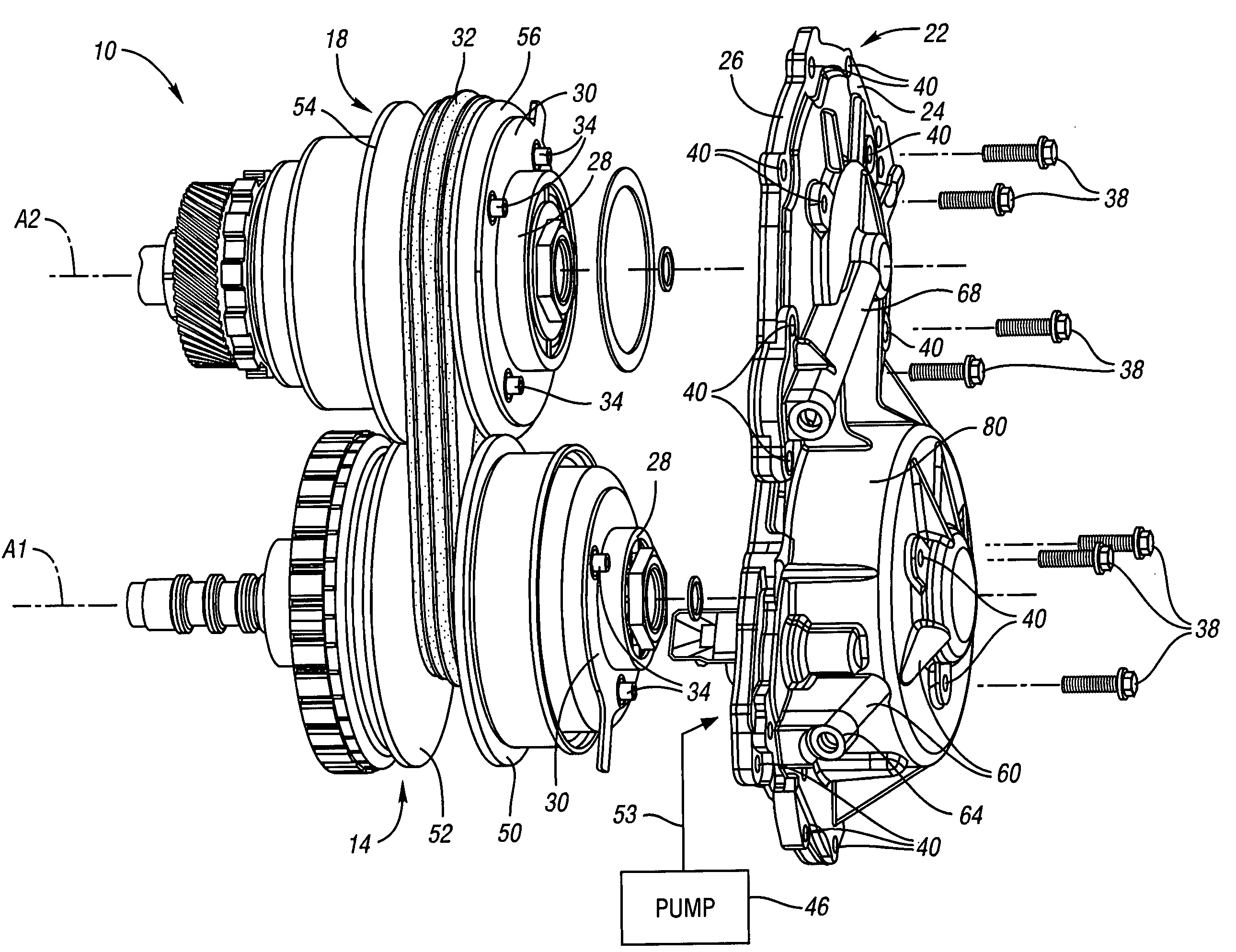
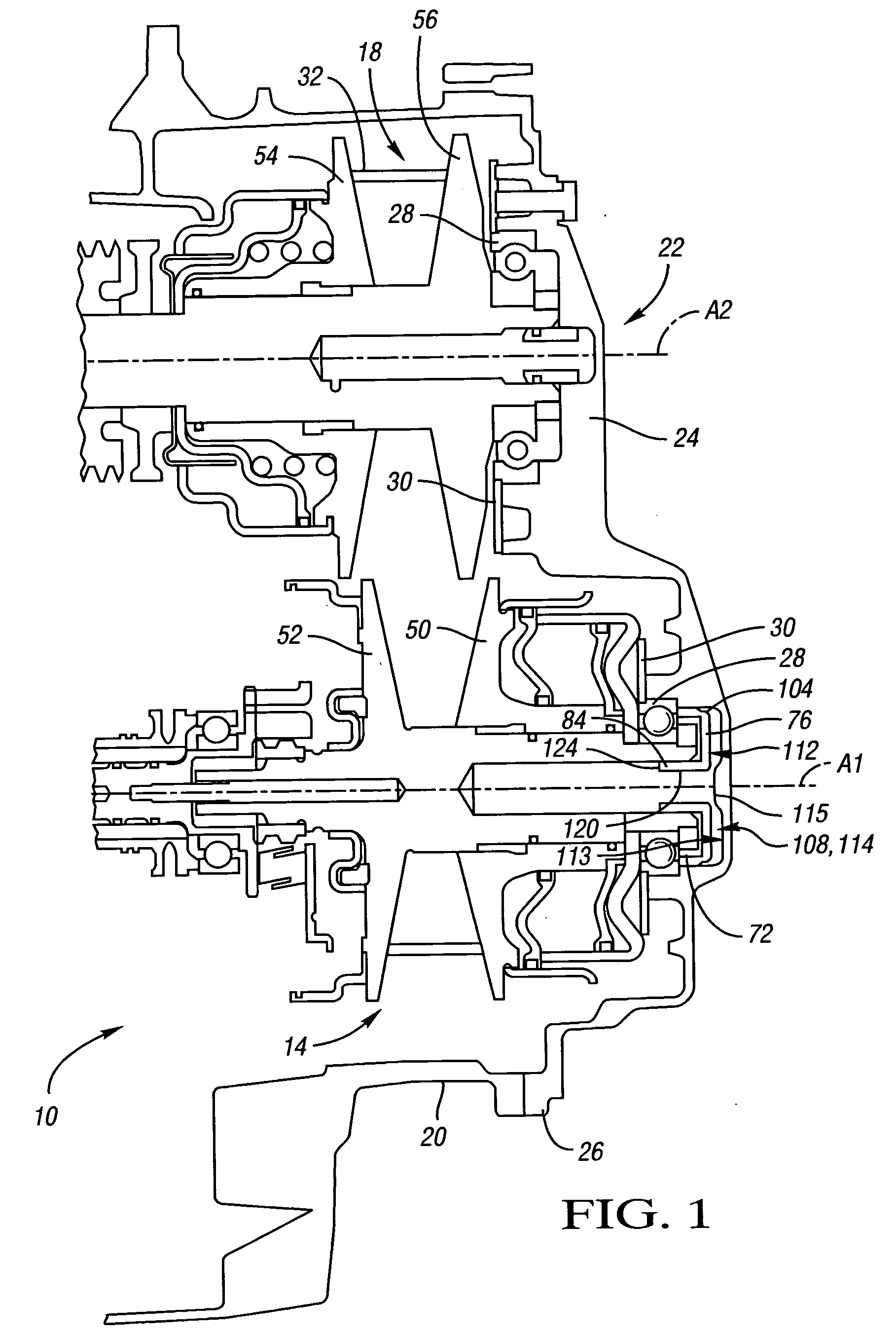
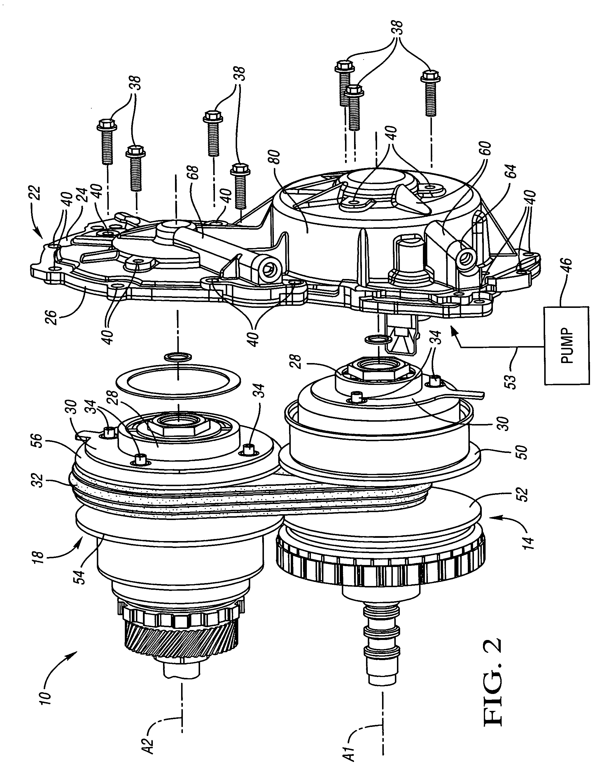
[0011] Referring to FIG. 1, a continuously variable transmission (CVT) 10 includes a drive sheave assembly 14 and a driven sheave assembly 18 at least partially contained in a transmission case 20. A case cover assembly 22 includes a case cover member 24 with an attachment flange 26 at which the case cover member 24 is affixed to the case 20 to close and seal the case.

[0012] The sheave assemblies 14, 18 each include a bearing 28 and a bearing retainer 30 at which the sheave assemblies 14, 18 are rotatably mounted to the case cover member 24. Drive sheave assembly 14 is rotatable about axis A1. Driven sheave assembly is rotatable about axis A2. The drive sheave assembly 14 is driven by an engine crankshaft (not shown) via a transmission input shaft and clutch or torque converter. The driven sheave assembly 18 is drivingly connected with vehicle drive wheels (not shown). The drive sheave assembly 14 and the driven sheave assembly 18 are interconnected by a flexible transmitter such a...


PUM


Abstract

A case cover assembly to which a sheave for a continuously variable transmission is mountable for rotation about an axis is configured to provide fluid communication between the sheave and a pressurized fluid source. The case cover assembly includes a conduit defining a first segment of a passageway for providing fluid communication between the pressurized fluid source and the sheave. An inner annular surface and an outer annular surface define an annular second segment of the passageway. A chamber at least partially formed by a case cover member defines a third segment of the passageway. The third segment is positioned with respect to the second segment such that fluid flows radially inward toward the axis from the second segment. The radial inflow provides improved pressure transference and packaging compared to the prior art.

Description

TECHNICAL FIELD [0001] This invention relates to case covers for continuously variable transmissions that are configured to convey hydraulic fluid from a pressurized fluid source to a sheave, and to minimize pressure losses by employing radial inflow channeling. BACKGROUND OF THE INVENTION [0002] Continuously variable transmissions (CVT) of the variable pulley or sheave type include an input sheave assembly and an output sheave assembly operatively interconnected by a flexible transmitter, such as a belt or chain. Each of the sheave assemblies has a piston in fluid communication with a pressurized fluid source, and is configured such that the distance from the sheave assembly's axis of rotation to where the flexible transmitter engages the sheave assembly is responsive to fluid pressure acting on the piston. Thus, the transmission ratio is varied by selectively changing the fluid pressure acting on each sheave assembly's piston. [0003] Each sheave assembly is rotatable about an axis...

Claims


Application Information

Patent Timeline
IPC IPC(8): B62J13/00F16D1/00F16H9/18F16H57/02F16H9/24F16H55/56F16H57/04F16H61/00F16H61/662
CPCB62J13/00F16H9/18F16H57/021F16H57/035Y10T74/2186F16H57/0445F16H61/662F16H2057/02043F16H2057/02086F16H57/0421
Inventor SCHOENEK, NORMANHARSCH, CHARLES
Owner GM GLOBAL TECH OPERATIONS LLC
Why Eureka
Try Eureka