Traction balloon

Inactive Publication Date: 2005-10-27
BOSTON SCI SCIMED INC
View PDF21 Cites 24 Cited by
  • Summary
  • Abstract
  • Description
  • Claims
  • Application Information

AI Technical Summary

Benefits of technology

[0005] The present invention relates to angioplasty balloon catheters. In at least some embodiments, an example balloon catheter may include a catheter shaft having a balloon coupled thereto. A traction member may be coupled to the shaft and/or a portion of the balloon and

Problems solved by technology

Heart and vascular disease are major problems in the United States and throughout the world.
Conditions such as atherosclerosis result in blood vessels becoming blocked or narrowed.
This blockage can result in lack of oxyg

Method used


Image

  • Traction balloon
  • Traction balloon
  • Traction balloon

Examples


Embodiment Construction

[0021] The following description should be read with reference to the drawings wherein like reference numerals indicate like elements throughout the several views. The detailed description and drawings illustrate example embodiments of the claimed invention.

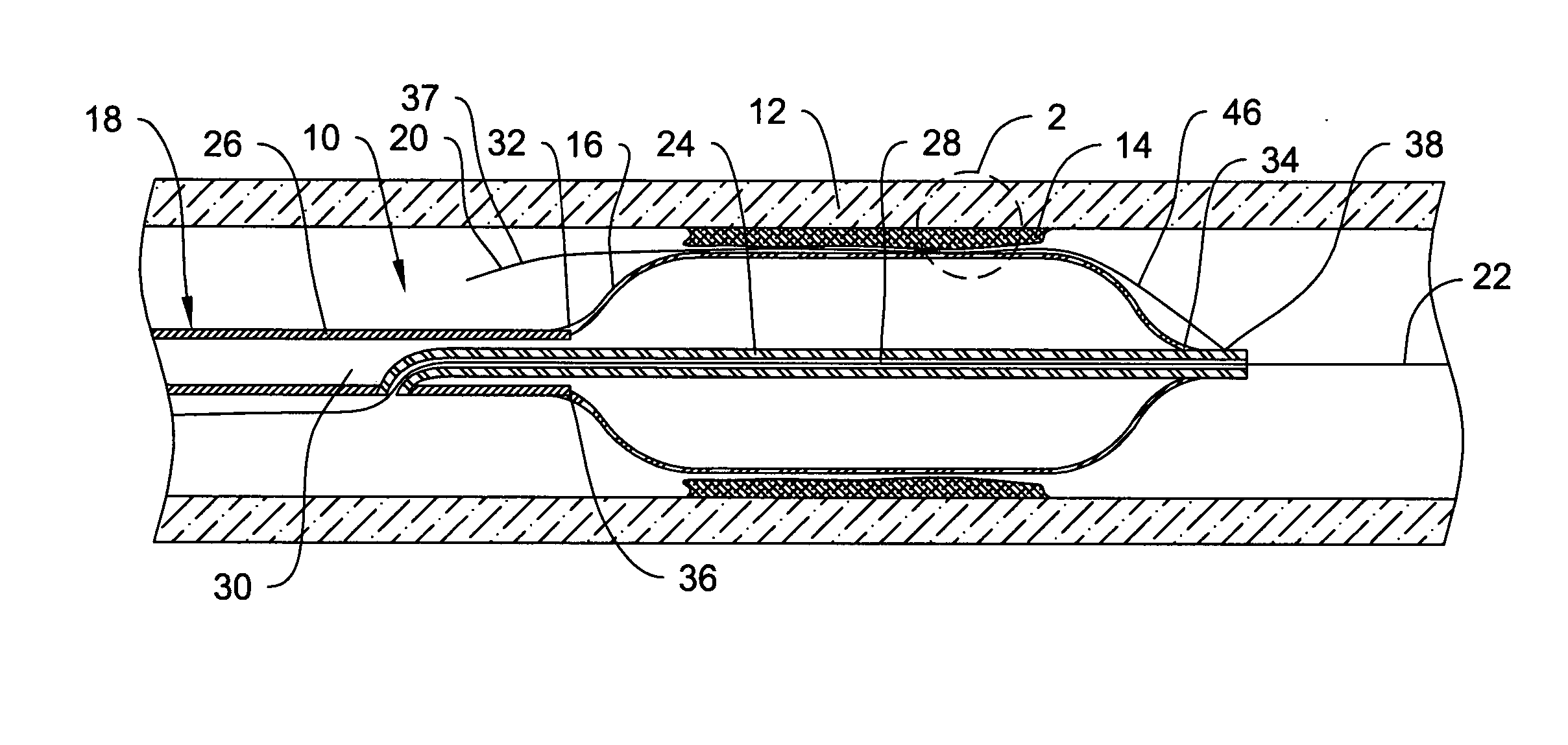
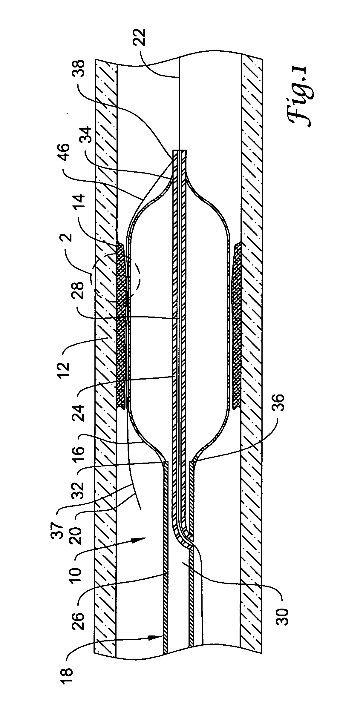
[0022] Angioplasty techniques have been shown to be effective for at least some intravascular interventions. FIG. 1 illustrates an example angioplasty catheter 10 positioned in a blood vessel 12 adjacent an intravascular lesion 14. Catheter 10 may include a balloon 16 coupled to a catheter shaft 18. A traction member 20 may be coupled to shaft 18 and / or balloon 16. In general, catheter 10 may be advanced over a guidewire 22 through the vasculature to a target area. Balloon 16 can then be inflated to expand lesion 14. The target area may be within any suitable peripheral or cardiac location.

[0023] In at least some embodiments, balloon 16 may be manufactured from a lubricious material. Alternatively, the balloon 16 may be coated ...


PUM


Abstract

Balloon catheters and methods of making and using the same. A balloon catheter may include a catheter shaft and a balloon coupled thereto. A traction member may be coupled to the balloon catheter adjacent the balloon and may extend along a portion or all of the length of the balloon. The traction member can improve traction between the balloon and a target site.

Description

FIELD OF THE INVENTION [0001] The present invention pertains to angioplasty and angioplasty balloon catheters. More particularly, the present invention pertains to angioplasty balloon catheters that include a shaft or traction member disposed adjacent the balloon for increasing the traction between the balloon and a target site. BACKGROUND OF THE INVENTION [0002] Heart and vascular disease are major problems in the United States and throughout the world. Conditions such as atherosclerosis result in blood vessels becoming blocked or narrowed. This blockage can result in lack of oxygenation of the heart, which has significant consequences since the heart muscle must be well oxygenated in order to maintain its blood pumping action. [0003] Occluded, stenotic, or narrowed blood vessels may be treated with a number of relatively non-invasive medical procedures including percutaneous transluminal angioplasty (PTA), percutaneous transluminal coronary angioplasty (PTCA), and atherectomy. Ang...

Claims


Application Information

Patent Timeline
IPC IPC(8): A61F2/958A61M29/02
CPCA61M2025/1086A61M25/10
Inventor MCAULEY, STEVEN A.CHEVES, KAREN M.CROW, LOREN M.KELLEY, GREGORY S.RADISCH, HERBERT R. JR.ROMAN, RICARDO DAVIDWU, SHOW-MEAN
Owner BOSTON SCI SCIMED INC
Why Eureka
Try Eureka