Apparatus and method for reducing the heat rate of a gas turbine powerplant

a gas turbine and heat rate technology, applied in the field of gas turbine engines, can solve the problems of high cost of gas turbine operation, high cost of maintenance, and fuel burned in the gas turbine, and achieve the effects of reducing pressure loss, improving efficiency, and increasing supply pressur

Active Publication Date: 2005-11-03
ANSALDO ENERGIA SWITZERLAND AG
View PDF9 Cites 24 Cited by
  • Summary
  • Abstract
  • Description
  • Claims
  • Application Information

AI Technical Summary

Benefits of technology

[0006] The present invention seeks to address the problems in the prior art by providing an apparatus and method for reducing the pressure loss of the air prior to entering a combustion system, such that, for a known combustion system having a predetermined pressure loss, the resulting fluid entering the turbine has a higher supply pressure, resulting in a more efficient turbine. In accordance with a preferred embodiment of the present invention, a gas turbine engine is provided comprising an axial compressor, an inner compressor discharge case proximate the compressor outlet, a plurality of combustors arranged in an annular array about the engine, and a turbine coupled to the compressor. The combustors include an outer case, a flow sleeve positioned within the outer case, a combustion liner positioned within the flow sleeve, an end cover having a plurality of fuel nozzles fixed to the outer case, and an exposed single-wall transition duct in fluid communication with the combustion liner. The exposed single-wall transition duct is positioned such that air from the compressor outlet is directed towards a first panel to provide direct cooling similar to a cylinder in cross flow geometry. The air is directed from the compressor outlet towards the transition duct by a deflector assembly comprising an inner deflector that is fixed to a first portion of the inner compressor discharge case and extends generally radially outward and an outer vane that is fixed to a second portion of the compressor discharge case.

Problems solved by technology

In addition to maintenance costs, one of the highest costs associated with operating a gas turbine at a powerplant, is the cost of the fuel burned in the gas turbine, either gas, liquid, or coal.
However, the geometry of the compressor discharge case 14 does not sufficiently direct the air from compressor 15 towards combustion system 10, and the air unnecessarily loses some of its supply pressure.
While this device may provide a more uniform flow to an impingement cooled device, it does not maximize the pressure recovery possible prior to entering the combustion system, which is a key element to improved engine efficiency and performance.

Method used


Image

  • Apparatus and method for reducing the heat rate of a gas turbine powerplant
  • Apparatus and method for reducing the heat rate of a gas turbine powerplant
  • Apparatus and method for reducing the heat rate of a gas turbine powerplant

Examples


Embodiment Construction

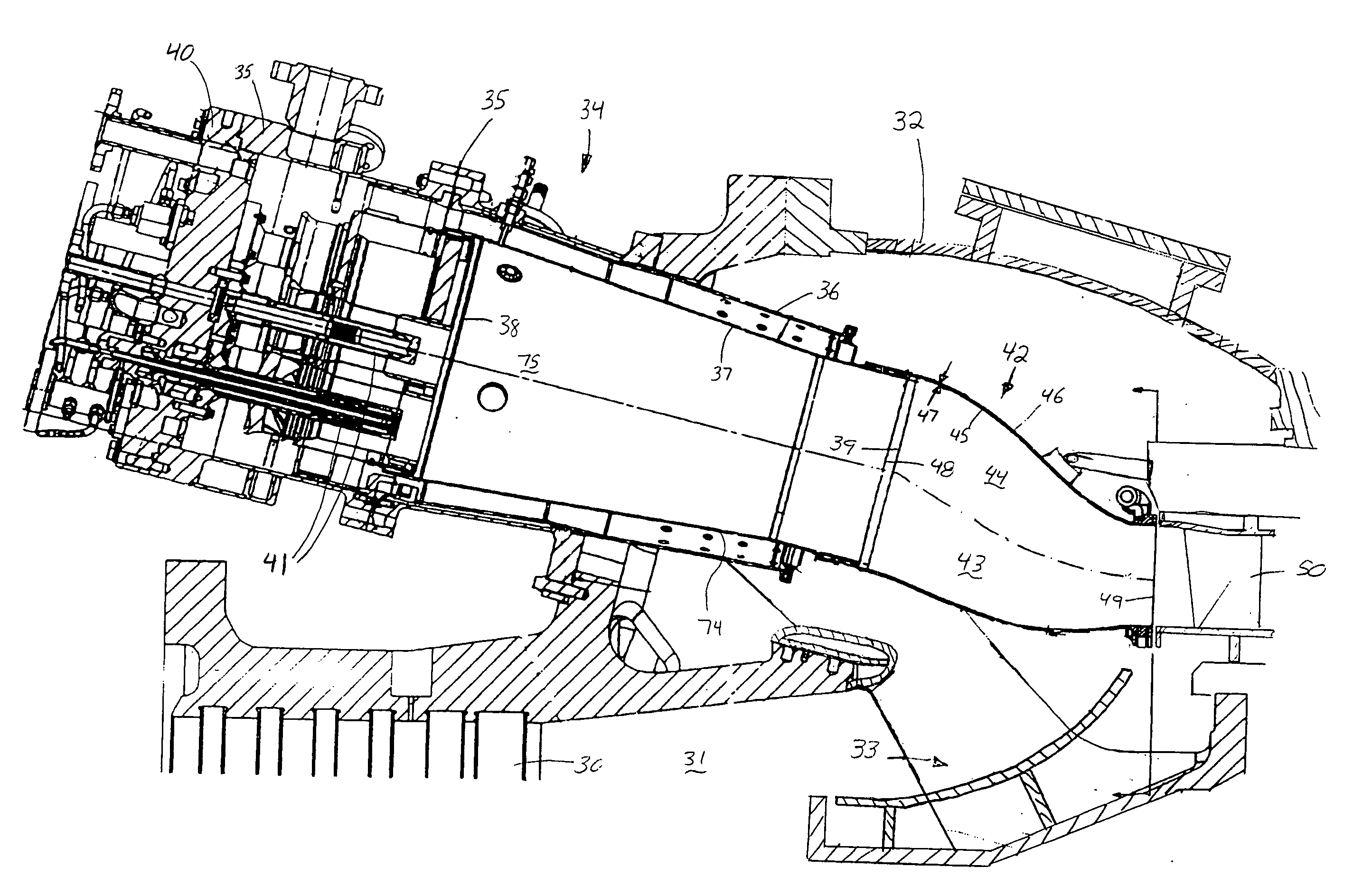
[0015] The preferred embodiment of the present invention is shown in cross section in FIG. 3. The present invention includes an apparatus and method for reducing the pressure drop and corresponding heat rate for a gas turbine engine with the apparatus comprising an axial compressor 30 that is coupled to an axially extending shaft (not shown) with compressor 30 having a compressor inlet (not shown) and a compressor outlet 31. Positioned proximate compressor outlet 31 for receiving air from compressor 30 is a compressor discharge case 32. Case 32 also incorporates a means for directing air 33 from compressor outlet 31 away from the compressor shaft and towards a plurality of combustors 34. The plurality of combustors is arranged in a generally annular array about the shaft, fixed to compressor discharge case 32, and comprise an outer case 35, a flow sleeve 36 positioned radially within outer case 35, and a combustion liner 37 positioned radially within flow sleeve 36 with combustion l...


PUM


Abstract

The present invention provides an apparatus and method for reducing the pressure loss of air prior to entering a combustion system, such that, for a known combustion system having a predetermined pressure loss, the resulting fluid entering the turbine has a higher supply pressure that will result in more efficient turbine and increased engine output. Significant enhancements include the addition of a plurality of deflector assemblies to direct the air from a compressor outlet towards an exposed single-wall transition duct to provide direct cooling to a first panel of the transition duct.

Description

TECHNICAL FIELD [0001] This invention primarily applies to gas turbine engines used to generate electricity and more specifically to a method and apparatus for reducing the heat rate and improving the overall efficiency. BACKGROUND OF THE INVENTION [0002] Operators of gas turbine engines used in generating electricity at powerplants desire to have the most efficient operations possible in order to maximize their profitability and limit the amount of emissions produced and excess heat lost. In addition to maintenance costs, one of the highest costs associated with operating a gas turbine at a powerplant, is the cost of the fuel burned in the gas turbine, either gas, liquid, or coal. For example, a gas turbine engine that operates on natural gas and is designed to produce approximately 170 MW of electricity when operated at base load, or full power throughout the year, typically consumes about 15.4 billion standard cubic feet of natural gas in a year. Increasing the efficiency of the ...

Claims


Application Information

Patent Timeline
Patent Type & Authority Applications(United States)
IPC IPC(8): F01D9/02F23R3/26F23R3/42F23R3/46
CPCF01D9/023F23R3/46F23R3/26
Inventor MARTLING, VINCENT C.XIAO, ZHENHUA
Owner ANSALDO ENERGIA SWITZERLAND AG
Why Eureka
Try Eureka