Diagnosis method for liquefied petroleum injection fuel pump

Inactive Publication Date: 2005-11-03
HYUNDAI MOTOR CO LTD
View PDF6 Cites 8 Cited by
  • Summary
  • Abstract
  • Description
  • Claims
  • Application Information

AI Technical Summary

Benefits of technology

[0004] The present invention sets the diagnosis time (the wait time after which the diagnosis occurs) of a fuel pump driver signal in an interface box to a duration longer than the time an e

Problems solved by technology

This conventional system however has a clear drawback, particularly when using a fuel pump driver, which is deactivated when its relay power is insulated by turning off an LPG switch.
For instance, after turning off the LPG switch while the ignition

Method used


Image

  • Diagnosis method for liquefied petroleum injection fuel pump
  • Diagnosis method for liquefied petroleum injection fuel pump
  • Diagnosis method for liquefied petroleum injection fuel pump

Examples


Example

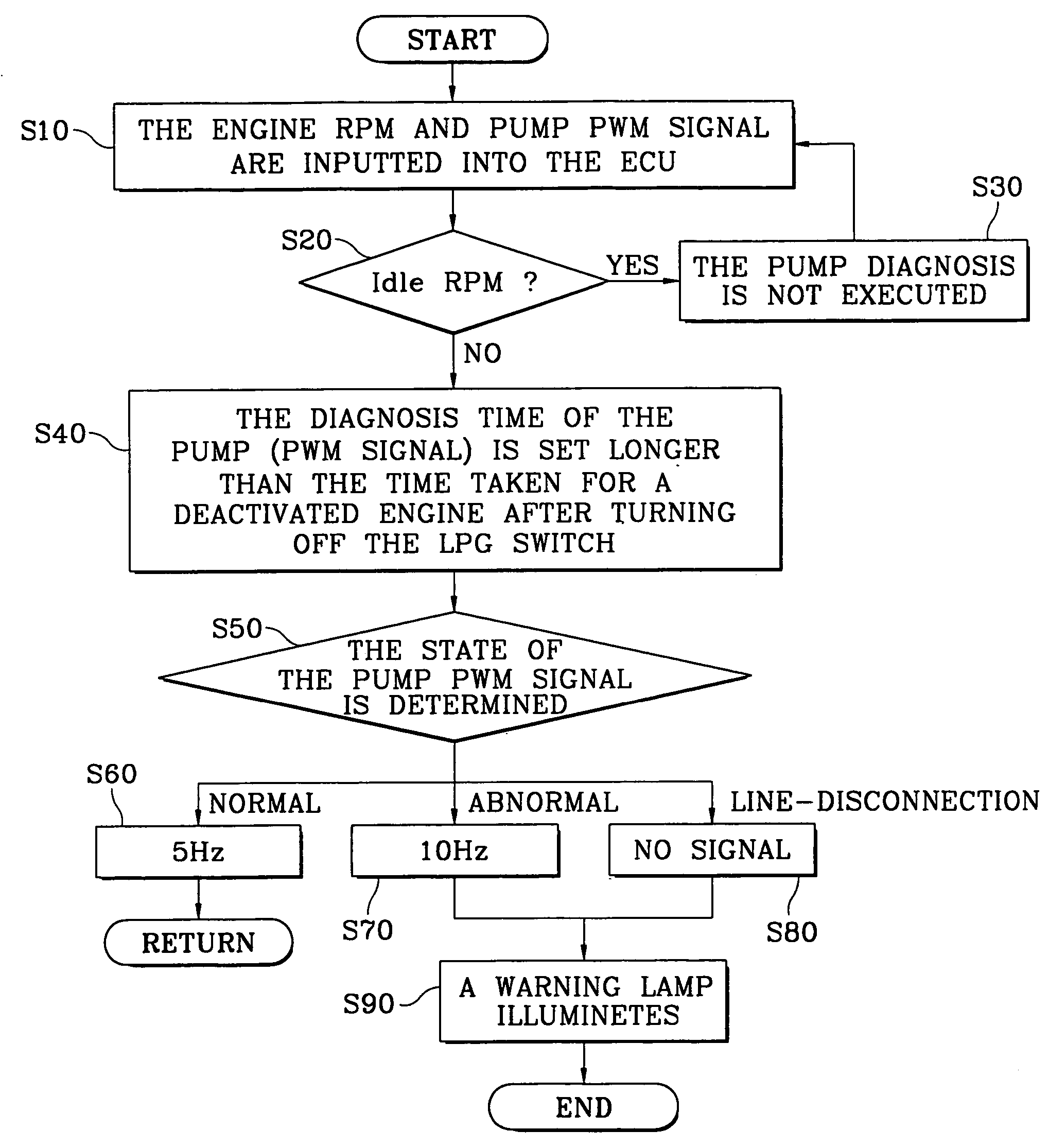
[0009] Referring to FIG. 1, the present invention includes the following steps for diagnosing a Liquefied Petroleum Injection (LPI) fuel pump. An Electronic Control Unit (ECU) of an interface box receives the present engine Revolutions Per Minute (RPM) and a signal (Pulse Width Modulation: PWM signal) from a fuel pump driver (step 10). Before diagnosing the PWM signal from the fuel pump driver, determining whether the engine is idling, based upon the RPM (step 20). As is well known to one who works in this field, the idle rpm according to the embodiment of the present invention means a minimum engine RPM with the ignition of the vehicle being on, and the idle rpm typically refers to approximately 600-900 rpm. If the engine is idling, the diagnosis of the fuel pump is not executed irregardless of the on and off state of a Liquefied Petroleum Gas (LPG) switch (step 30).

[0010] However, if the engine is not idling (i.e., when the vehicle is in motion), a diagnosis time (the wait time a...


PUM


Abstract

A method for diagnosing a Liquefied Petroleum Injection fuel pump includes the steps of: inputting an engine Revolutions Per Minute (RPM) and a fuel pump Pulse Width Modulation (PWM) signal into an Electronic Control Unit (ECU) of an interface box; determining whether the RPM indicates that the engine is idling; if the engine is not idling, setting a diagnosis time of the PWM signal to a duration longer than the time the engine takes to deactivate after turning off an LPG switch; determining the operation state of the fuel pump by analyzing the PWM signal; and illuminating a warning lamp if the fuel pump is detected to be operating abnormally or a signal line connecting the fuel pump and the interface box is detected to be disconnected.

Description

CROSS-REFERENCE TO RELATED APPLICATIONS [0001] The present application is based on, and claims priority from, Korean Application Serial Number 10-2004-0029977, filed on Apr. 29, 2004, the disclosure of which is hereby incorporated by reference herein in its entirety. FIELD OF THE INVENTION [0002] The present invention relates to a method of diagnosing a vehicle Liquefied Petroleum Injection (LPI) fuel pump whereby an erroneous diagnosis of the fuel pump due to a turned off state of a Liquefied Petroleum Gas (LPG) switch is prevented. More particularly, the present invention relates to an interface box that receives a Pulse Width Modulation (PWM) signal from a fuel pump driver and then prolongs the period of time of diagnosing the operation state of the fuel pump. BACKGROUND OF THE INVENTION [0003] In a Liquefied Petroleum Injection (LPI) system, Liquefied Petroleum Gas (LPG) fuel is generally directly injected into the vehicle engine to improve the engine output and reduce exhaust g...

Claims


Application Information

Patent Timeline
IPC IPC(8): F02M21/02F02D41/22F02D41/30F02D45/00F02M37/08F02M65/00G01M15/00
CPCF02D41/22F02M65/00F02D2200/0611F02D41/3082
Inventor SHIN, CHANG-HYUNCHOI, HONG-SUK
Owner HYUNDAI MOTOR CO LTD
Why Eureka
Try Eureka