
Stereoscopic display apparatus

Inactive Publication Date: 2012-10-04
FUJIFILM CORP
View PDF8 Cites 6 Cited by
  • Summary
  • Abstract
  • Description
  • Claims
  • Application Information

AI Technical Summary

Benefits of technology

[0005]As described above, when a radiographic image is stereoscopically displayed, it is easy to determine locations in the depth direction. However, for example, when a stereoscopic display providing an excessively-protruding view is observed, this can increase eye fatigue or even cause erroneous diagnosis in some cases.
[0007]An object of the present invention is to provide a stereoscopic display apparatus which can simply change the depth of a stereoscopic display in a right-eye image and a left-eye image radiographed (stereoscopically photographed) for the purpose of a stereoscopic display.
[0033]According to the present invention, since the depth of a stereoscopic display can be freely changed in the range in which the stereoscopic view is not destroyed, it is possible to reduce the burden on the eyes when viewing the stereoscopic display, and thus to prevent erroneous diagnosis due to the eye fatigue.

Problems solved by technology

However, for example, when a stereoscopic display providing an excessively-protruding view is observed, this can increase eye fatigue or even cause erroneous diagnosis in some cases.

Method used


Image

  • Stereoscopic display apparatus
  • Stereoscopic display apparatus
  • Stereoscopic display apparatus

Examples


first embodiment

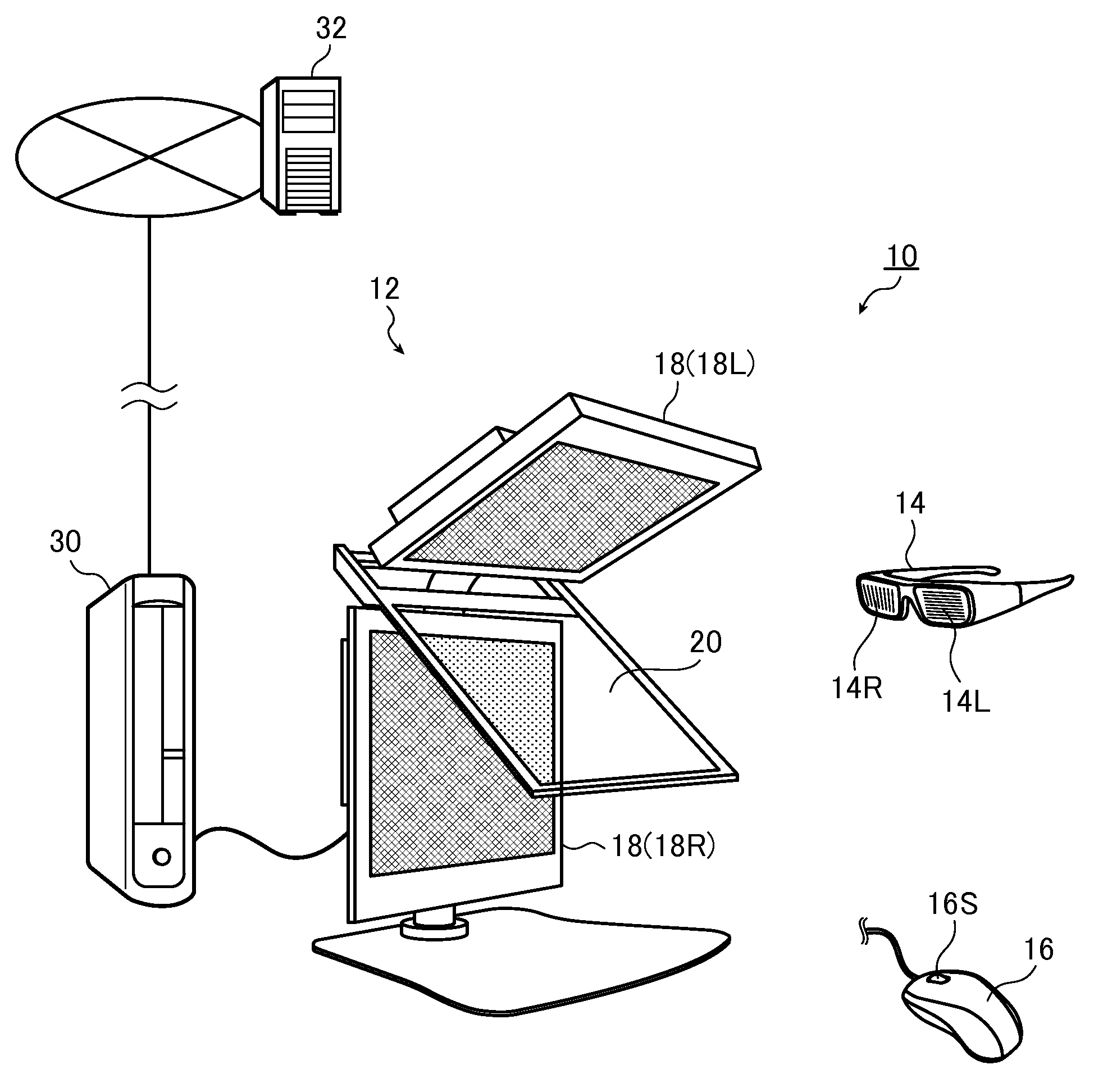
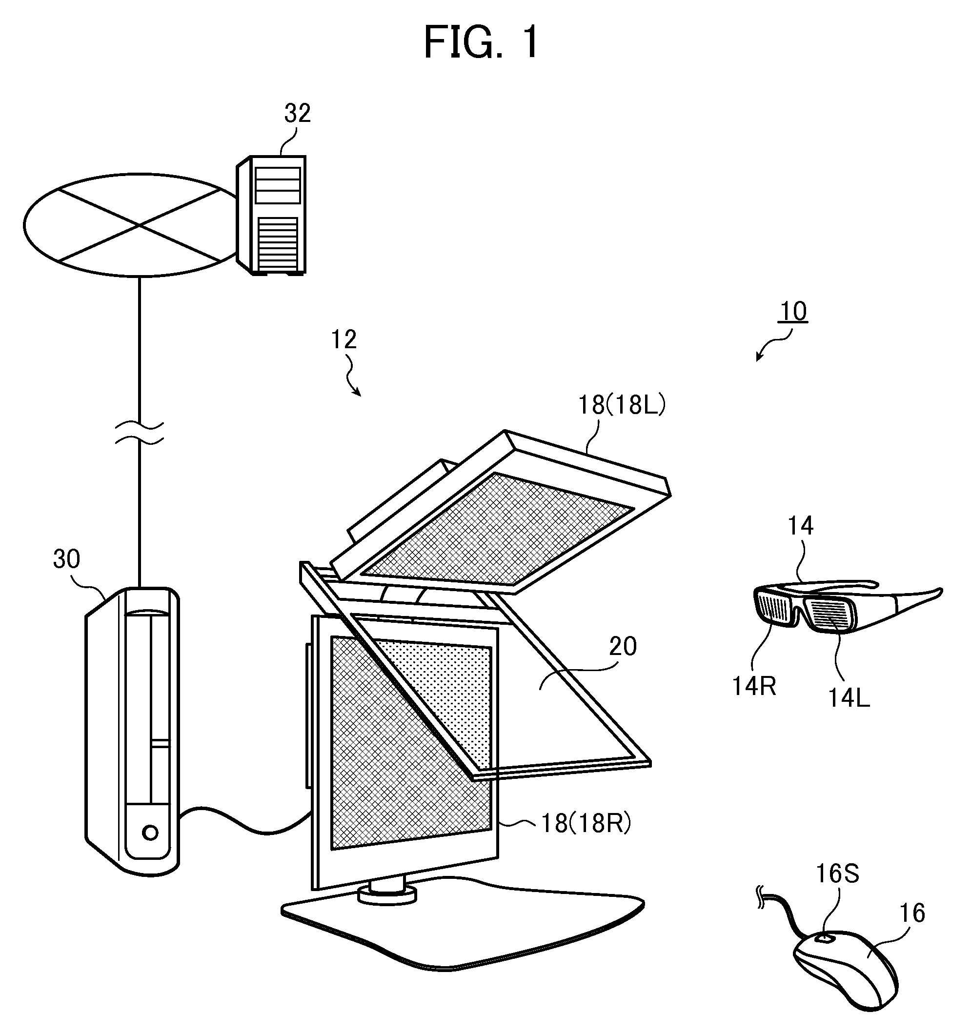
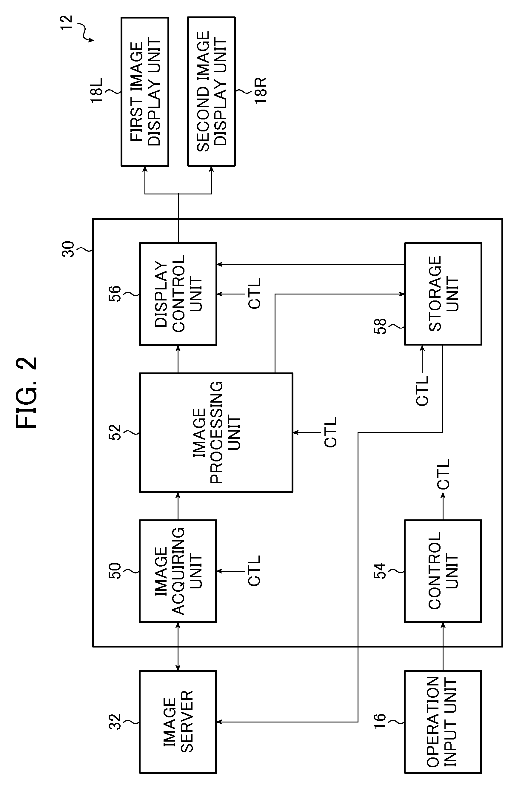
[0045]FIG. 1 is an overview diagram illustrating the entire configuration of an example of a stereoscopic display apparatus according to the present invention. FIG. 2 is a block diagram illustrating an example of the system configuration of the stereoscopic display apparatus according to the present invention.

[0046]The stereoscopic display apparatus 10 according to the present invention includes a display unit 12, a pair of polarizing glasses 14, an operation input unit 16, and a console 30.

[0047]The display unit 12 includes a first image display unit 18L, a second image display unit 18R, and a beam splitter mirror 20. The display unit 12 performs a stereoscopic display by displaying a left-eye image on the first image display unit 18L and displaying a right-eye image on the second image display unit 18R, and may also display a normal planar display by displaying the same image on the first image display unit 18L and the second image display unit 18R.

[0048]In the first embodiment, i...

second embodiment

[0158]The configuration of the stereoscopic display apparatus according to the second embodiment of the present invention is the same as the stereoscopic display apparatus 10 according to the first embodiment shown in FIGS. 1 and 2 and thus description thereof will not be repeated.

[0159]The second embodiment is different from the first embodiment, in that conditions for display (display conditions), conditions for processing image (image processing conditions), and conditions for observation (including an observer) (observation conditions) are considered in addition to the radiographic conditions when calculating the maximum and minimum values in shift of the right-eye image and the left-eye image.

[0160]An enlargement ratio (enlargement and reduction ratio) based on the pixel size of the monitor (the display unit 12) can be considered as an example of the display conditions and a display magnification based on display software can be considered as an example of the image processing ...


PUM


Abstract

A stereoscopic display apparatus that performs a stereoscopic display using a right-eye image and a left-eye image acquired by radiographing a subject plural times while changing an incidence angle of radiation on the subject, includes a display unit that stereoscopically displays the right-eye image and the left-eye image, and a changing unit that shifts at least one of the right-eye image and the left-eye image displayed on the display unit to change an inter-image distance being a distance between the right-eye image and the left-eye image in a direction parallel to a straight line connecting the right eye and the left eye of an observer.

Description

BACKGROUND OF THE INVENTION[0001]This invention relates to a stereoscopic display apparatus that performs a stereoscopic display using a right-eye image and a left-eye image acquired through radiography (stereoscopic photography).[0002]Recently, medical image-related network systems such as PACS (Picture Archiving and Communication Systems) have been developed and opportunities for storing radiographic images during diagnosis as digital data in a server and using the digital data for follow-up later or transmitting the radiographic images during the previous diagnosis as image data for use by other remote hospitals is increasing.[0003]In radiography, the invention of a stereoscopic display apparatus of a radiographic image that irradiates a subject with radiation from different angles, that acquires (stereoscopically photographs) a right-eye image and a left-eye image, and that performs a stereoscopic display using the acquired images is known.[0004]In fluoroscopic images such as ra...

Claims


Application Information

Patent Timeline
IPC IPC(8): G06T15/00H04N13/221
CPCH04N13/0022H04N13/0434H04N13/0497H04N13/0221G02B27/26H04N13/0475A61B6/022A61B6/466H04N13/0253H04N13/337H04N13/221H04N13/254H04N13/373H04N13/128H04N13/398G02B30/25
Inventor KANAGAWA, AKIKOKANEKO, YASUHIKOHIRUOKA, JUNSAKAGUCHI, YUICHIMOCHIZUKI, NAOKIIDA, NORIAKI
Owner FUJIFILM CORP
Learn More