
Gravure coating apparatus, and optical film

a coating apparatus and optical film technology, applied in coatings, printing, rotary intaglio printing presses, etc., can solve the problems of linear non-uniformity, inability to achieve sufficient performance of the coating apparatus, easy manifestation of non-uniformity, etc., and achieve the effect of preventing coating non-uniformity

Inactive Publication Date: 2005-11-03
FUJIFILM HLDG CORP
View PDF2 Cites 25 Cited by
  • Summary
  • Abstract
  • Description
  • Claims
  • Application Information

AI Technical Summary

Benefits of technology

[0011] Furthermore, since the coating layer is a thin layer, it is impossible to take sufficient time to level the liquid in order to eliminate the difference of the coating volume that causes the nonuniformity, leading to an easy manifestation of the nonuniformity.
[0013] The present invention has been created in view of these circumstances, and it is an object of the present invention to provide a state of stable coating where any nonuniformity appears even for the coating of a thin layer in the production of an optical film or the like by a gravure coating apparatus.
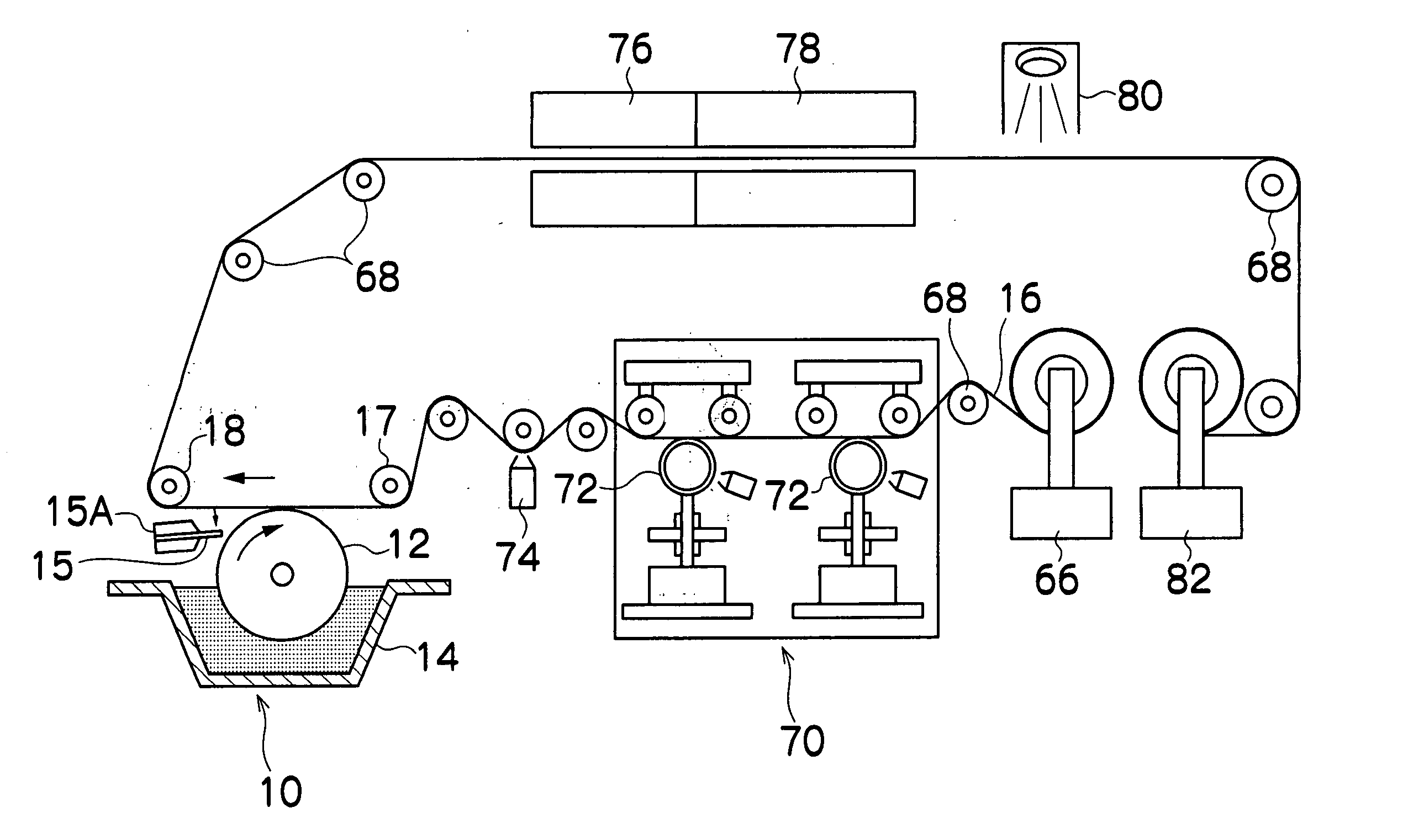
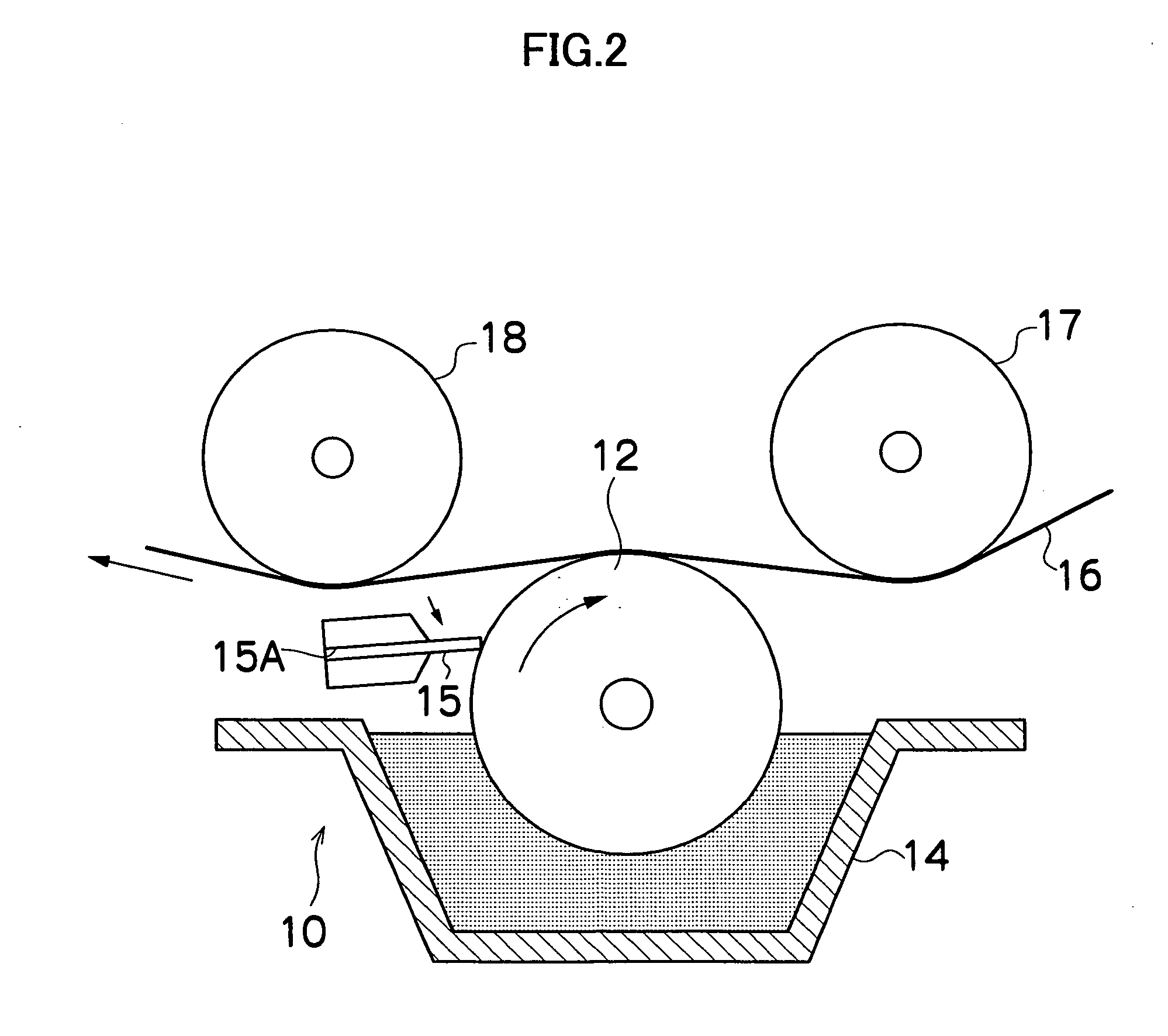
[0015] According to the present invention, since the gravure roller with no load has a radial run out of 15 μm or less in all places of a pattern part in which cells are formed (the gravure plate cylinder) on the surface of the gravure roller, liquid accumulations (beads) are hardly affected by the radial run out of the roller surface, thereby making it possible to prevent coating nonuniformity.
[0017] According to the present invention, since misalignment between the shaft center of a driving shaft connected to the end of the gravure roller and the shaft center of the gravure roller is small, liquid accumulations (beads) are hardly affected by the radial run out of the roller surface, thereby making it possible to prevent coating nonuniformity.
[0019] According to the present invention, since the gravure roller during coating has a radial run out of 30 μm or less in all places of a pattern part in which cells are formed (the gravure plate cylinder) on the surface of the gravure roller, liquid accumulations (beads) are hardly affected by the radial run out of the roller surface, thereby making it possible to prevent coating nonuniformity.
[0022] As described above, according to the present invention, liquid accumulations (beads) are hardly affected by the radial run out of the roller surface, thereby making it possible to prevent coating nonuniformity.

Problems solved by technology

However, even the above-described gravure coating apparatus cannot achieve sufficient performance under present circumstances.
Consequently, the radial run out of the gravure roller surface affects the liquid accumulations, often causing linear nonuniformity in a width direction of a web, which is a serious problem.
Furthermore, since the coating layer is a thin layer, it is impossible to take sufficient time to level the liquid in order to eliminate the difference of the coating volume that causes the nonuniformity, leading to an easy manifestation of the nonuniformity.
On the other hand, as described in the above-described Japanese Patent Application Laid-open No. 2003-56551, a method for improving rotational accuracy by devising a bearing part is proposed, but the method cannot cope with the run out of a gravure plate cylinder.

Method used


Image

  • Gravure coating apparatus, and optical film
  • Gravure coating apparatus, and optical film
  • Gravure coating apparatus, and optical film

Examples


examples

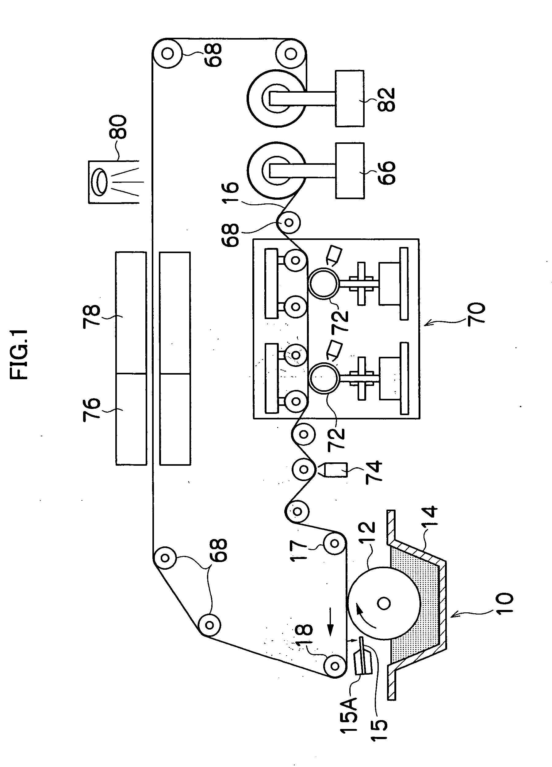
[0190] The gravure coating apparatus 10 shown in FIG. 2 was used to coat a coating liquid on the web 16 to produce an optical film (antiglare film).

[0191] A triacetyl cellulose (TAC) film having a thickness of 80 μm and a width of 1,000 mm was used as the web 16.

[0192] A coating liquid for an antiglare layer was prepared as described below. To 104 g of a mixed solvent consisting of methyl ethyl ketone / cyclohexanone=54 / 46% by weight, were dissolved 75 g of a mixture of dipentaerythritol pentaacrylate and dipentaerythritol hexaacrylate (DPHA from Nippon Kayaku Co., Ltd.) and 240 g of a hard-coating liquid containing a dispersion of zirconium oxide superfine particles with a particle size of about 30 nm (DeSolite Z-7401 from JSR Corporation).

[0193] To the resultant solution, was added and dissolved by stirring 10 g of a photopolymerization initiator (Irgacure 907 from Ciba Fine Chemicals K.K.). Then, to the resultant solution, was added 0.93 g of a fluorinated surfactant (Megafac F-...


PUM


Abstract

According to the present invention, since the gravure roller with no load has a radial run out of 15 μm or less in all places of a pattern part in which cells are formed (the gravure plate cylinder) on the surface of the gravure roller, liquid accumulations (beads) are hardly affected by the radial run out of the roller surface, thereby making it possible to prevent coating nonuniformity.

Description

BACKGROUND OF THE INVENTION [0001] 1. Field of the Invention [0002] The present invention relates to a gravure coating apparatus and optical films, in particular, to a gravure coating apparatus suitably applied to the production of optical films such as optical compensation films, antireflection films, antiglare films, optical films useful for improving the nonuniformity of liquid crystal layers, and to optical films produced by using the gravure coating apparatus. [0003] 2. Related Art [0004] In recent years, optical films are now in increasing demand. These optical films are typified by films with various functions such as optical compensation films used as phase difference plates for liquid crystal cells, antireflection films and antiglare films. [0005] A representative example of the method for producing these optical films includes a method in which coating films of various compositions are formed on a surface of a belt-like flexible substrate (hereinafter referred to as a “web...

Claims


Application Information

Patent Timeline
Patent Type & Authority Applications(United States)
IPC IPC(8): B05C1/00B05C1/08B05D1/28B41F9/06
CPCB05C1/08B41F9/063B05C1/0808
Inventor OGAWA, TOMONARIENDO, SHUICHIKODO, ATSUSHI
Owner FUJIFILM HLDG CORP
Learn More