Gas sensor

Inactive Publication Date: 2005-11-03
NGK SPARK PLUG CO LTD
View PDF4 Cites 30 Cited by
  • Summary
  • Abstract
  • Description
  • Claims
  • Application Information

AI Technical Summary

Benefits of technology

[0047] It is preferable that the plural number of guiding bodies are evenly arranged around the outer hollow-cylindrical portion, and that six or more number of guiding bodies are provided. The reason is because, if the number of the guiding bodies is less than six, when the positions of the guiding bodies opposite to the gas to be measured flowing around the protector are deviated to a circumferential direction of the protector, the swirling spee

Problems solved by technology

Therefore, replacement of the gas to be measured inside the protector is insufficient.
There is a problem in which response performance when detecting the gas components of the gas to be measured may be deteriora

Method used


Image

  • Gas sensor
  • Gas sensor
  • Gas sensor

Examples


first example

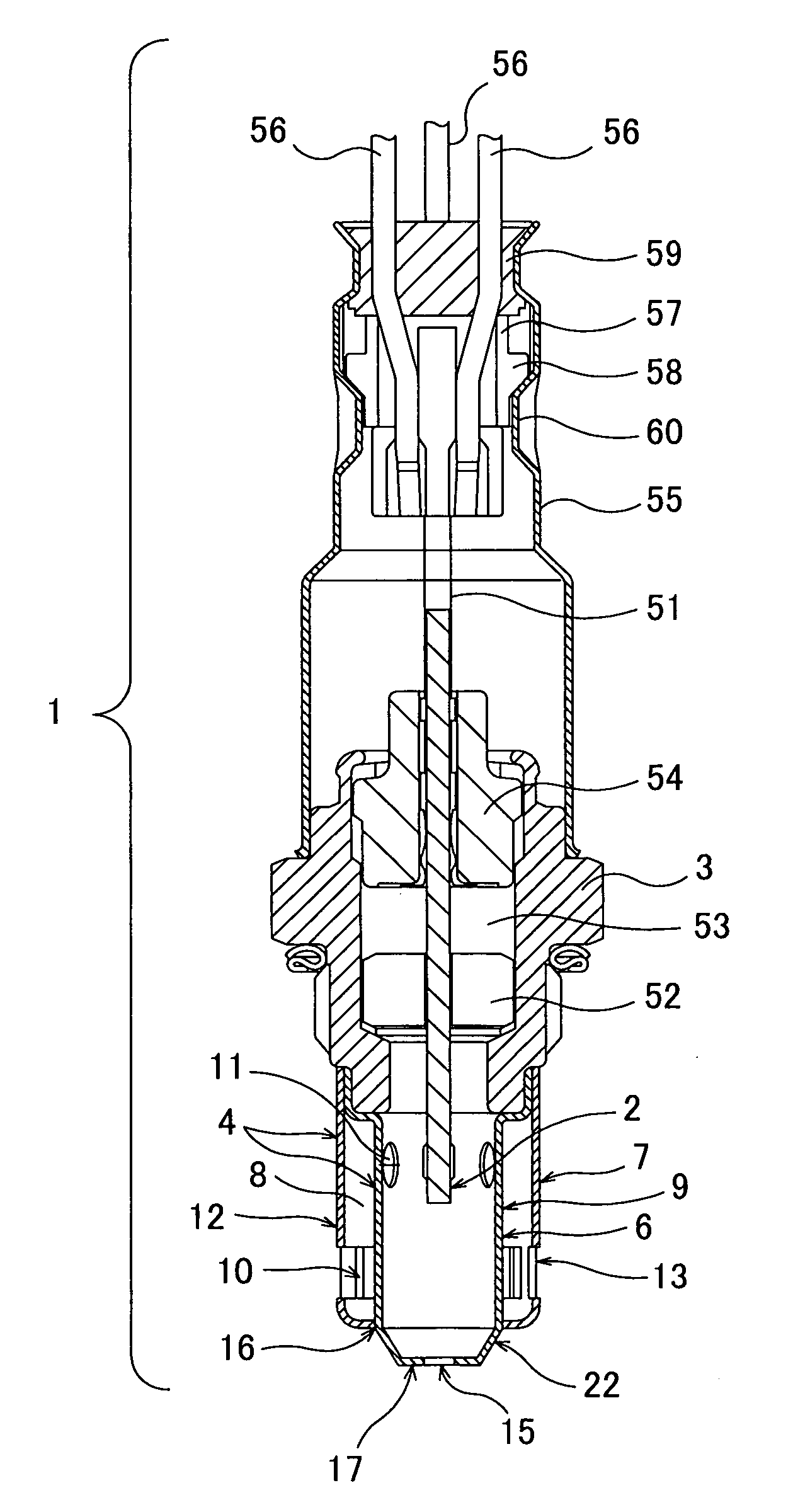
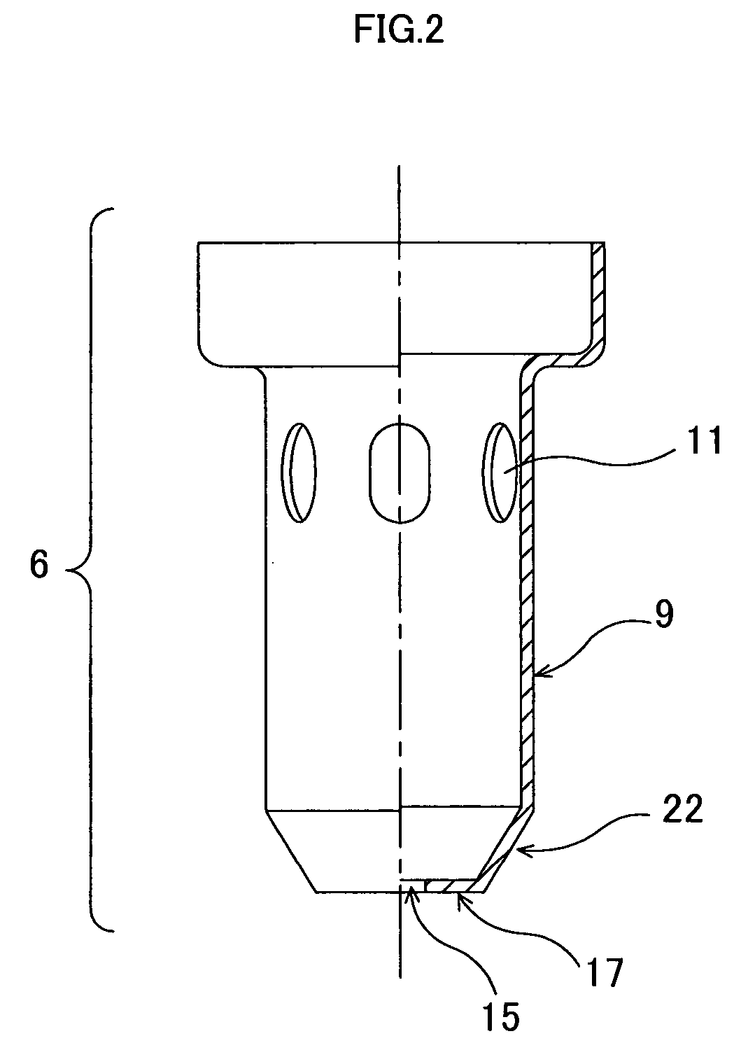
[0060]FIG. 1 is a cross sectional view showing a structure of a gas sensor of a first example according to the present invention according to the present invention. FIG. 2 is a half sectional view showing a shape of an inner hollow-cylindrical portion of the first example. FIG. 3 are, respectively, a half sectional view showing a shape of an outer hollow-cylindrical portion of the first example, and a cross sectional view taken along a line B-B in the foregoing figure.

[0061] Referring to FIGS. 1 to 3, a gas sensor 1 comprises a gas sensing element 2 that has a gas contact part, which is brought into contact with a gas to be measured, at a front end (lower side in the figures), a cylindrical case 3 that firmly holds the gas sensing element 2 in such a manner that the gas contact part protrudes from a front end of the case 3, and a bottomed cylindrical protector 4 that is fixed to the outer circumference at the front end of the case 3.

[0062] As shown in FIG. 1, the gas sensing eleme...

second example

[0086] Referring to FIG. 6, the gas sensor of a second example of the present invention is described. The gas sensor in the second example basically has the same structure as the gas sensor described in the first example. Therefore, the same reference numbers are given to the components in common, and detailed descriptions on the same are not repeated. Only the distinguishing parts are explained.

[0087] As shown in FIG. 6, a gas sensor 27 comprises a protector 5. The protector 5 has a two-tiered structure composed of an inner hollow-cylindrical portion 28 and a outer hollow-cylindrical portion 29 that is coaxially provided outside the inner hollow-cylindrical portion 28 with an air space 8 in between.

[0088] The outer hollow-cylindrical portion 29 has a first bottom wall 19 that is provided nearer to the front end than an end part (front end part) 16 of the inner hollow-cylindrical portion 28, and a second bottom wall 32 that is provided nearer to the front end than the first bottom...

third example

[0091] Referring to FIGS. 7A and 7B, the gas sensor of a third example of the present invention is described. FIG. 7A is a cross sectional view showing a structure of a gas sensor of the third example according to the present invention. FIG. 7B is a cross sectional view taken along the Y-Y in FIG. 7A. The gas sensor in the third example basically has the same structure as the gas sensor of the first example. Therefore, the same reference numbers are given to the components in common, and detailed descriptions on the same are not repeated. Only the distinguishing parts are explained.

[0092] As shown in FIG. 7A, a gas sensor 1A is provided with second drain holes 61 in the side wall of the inner hollow-cylindrical portion 6. In the second drain holes 61, a front side edge 61a of the inner circumferential edge of the second drain holes 61 is formed nearer to the front end side in a direction of axis Z of the protector 4 than the rear side edge 13a of the inner circumferential edge of t...


PUM


Abstract

A gas sensor is constructed as follows. A protector (4) covering around a gas sensing element (2) has an inner hollow-cylindrical portion (6) and an outer hollow-cylindrical portion (7) that is provided coaxially with the inner hollow-cylindrical portion (6) with an air space (8) in between. Outer-wall gas inlet openings (13) are formed in the outer hollow-cylindrical portion (7), and guiding bodies (10) extending inward are attached to the outer-wall gas inlet openings (13). Inner-wall gas inlet openings (11) are formed in the inner hollow-cylindrical portion (6) at positions nearer to the gas sensing element (2) than the outer-wall gas inlet openings (13). A side wall (9) face of the inner hollow-cylindrical portion (6) opposite the outer-wall gas inlet openings (13) is formed so as to be parallel to a side wall (12) of the outer-hollow cylindrical portion (7) or so as to have a slop-like shape with a diameter enlarging in the axial direction toward a bottom wall (17) of the protector (4). A discharge opening (15) for a gas to be measured is formed in the bottom wall (17).

Description

TECHNICAL FIELD [0001] This invention relates to a gas sensor, such as an oxygen sensor and a NOx sensor, which is used in a state exposed to a gas to be measured, and which comprises a protector that protects a gas sensing element accommodated therein from moisture contained in the gas to be measured. BACKGROUND ART [0002] Heretofore, gas sensors have been developed which are attached to an internal combustion, like an automobile engine, and detect specific gas components in exhaust gas (a gas to be measured). Among such gas sensors, a gas sensor (oxygen sensor), which detects oxygen concentration, and a NOx sensor, which detects nitric oxide gas concentration, are known to use a gas sensing element composed of a solid electrolyte such as zirconia. [0003] Generally, the gas sensors of this type have a structure in which a gas contact part of the gas sensing element is exposed to the exhaust gas. The gas sensing element is heated to high temperatures (approximately 300° C.) by a hea...

Claims


Application Information

Patent Timeline
IPC IPC(8): G01N27/407
CPCG01N27/4077
Inventor SHICHIDA, TAKAFUMIYOSHIKAWA, TAKAYANAKASHIMA, TAKASHIISHIKAWA, SATOSHI
Owner NGK SPARK PLUG CO LTD
Why Eureka
Try Eureka