Automatic brake mechanism

Inactive Publication Date: 2005-11-03
SUPERWINCH
View PDF24 Cites 8 Cited by
  • Summary
  • Abstract
  • Description
  • Claims
  • Application Information

AI Technical Summary

Benefits of technology

[0008] The brake avoids the application of a braking force directly to the inside surface of the rotating member or drum. Instead, a female truncated cone is fixed within the cavity of the rotating member, and is engaged by a corresponding male truncated cone for braking action. Axial actuation of the male truncated cone forces the male cone against a frictional material applied to the female truncated cone, thereby contr

Problems solved by technology

However, difficulties with conventional winch brake designs include high cos

Method used


Image

  • Automatic brake mechanism
  • Automatic brake mechanism
  • Automatic brake mechanism

Examples


Embodiment Construction

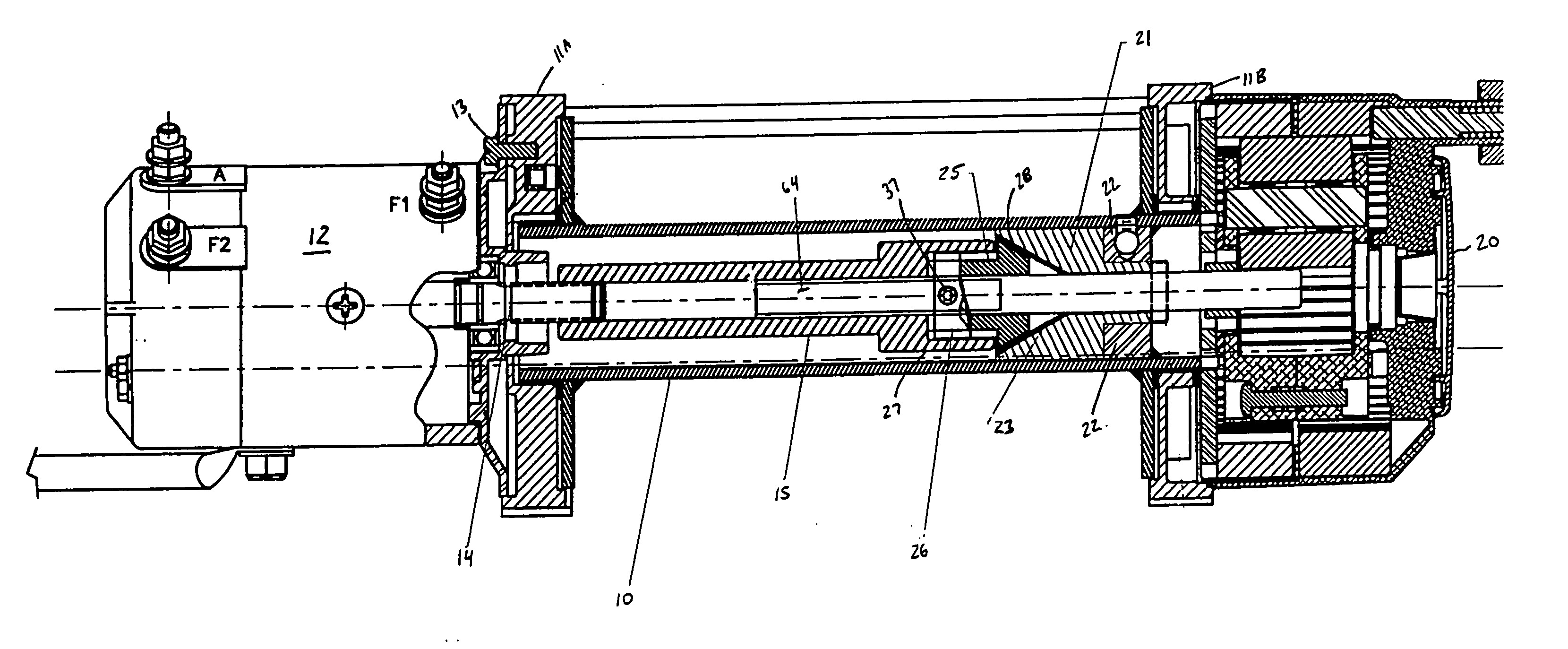
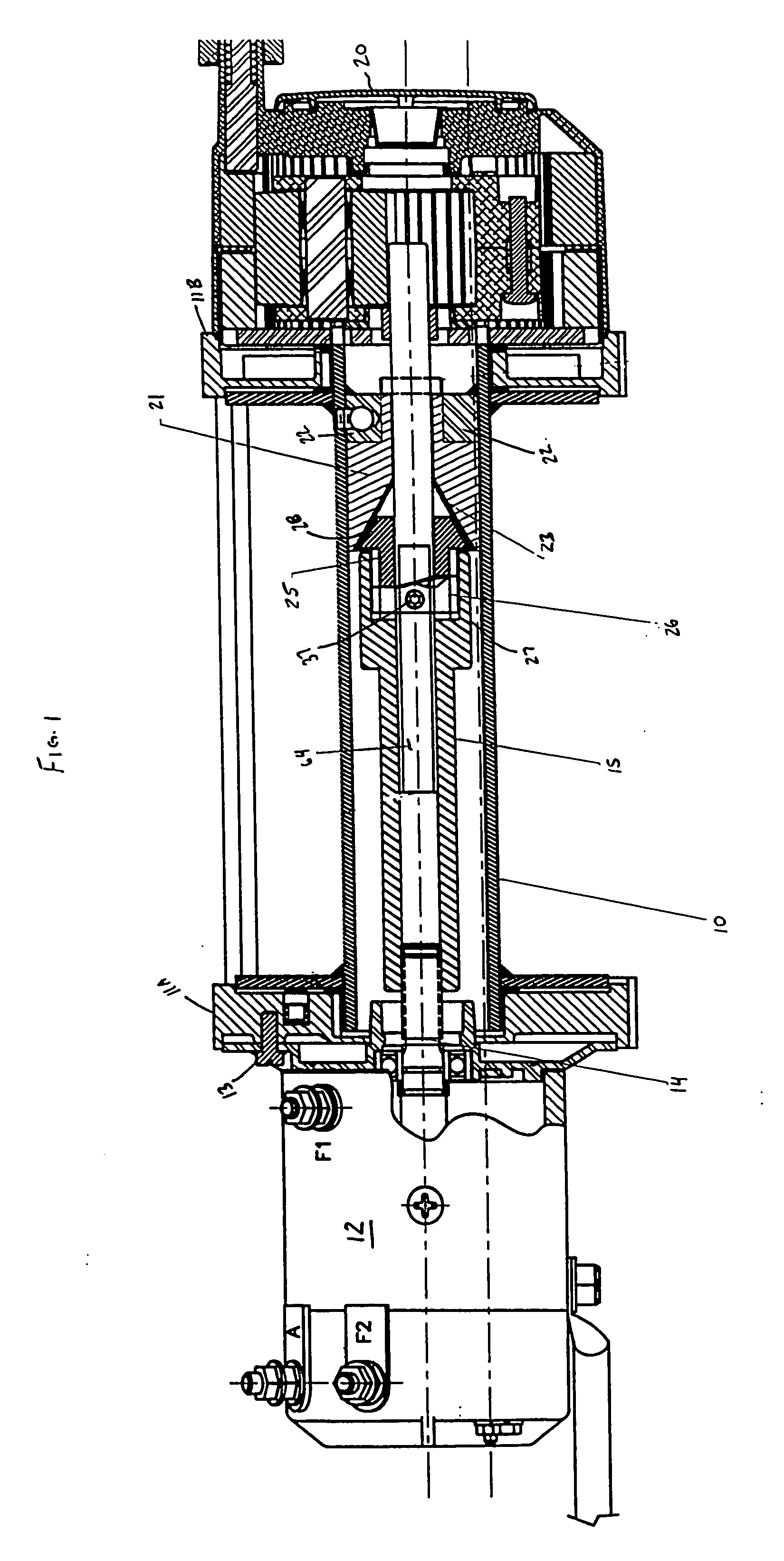
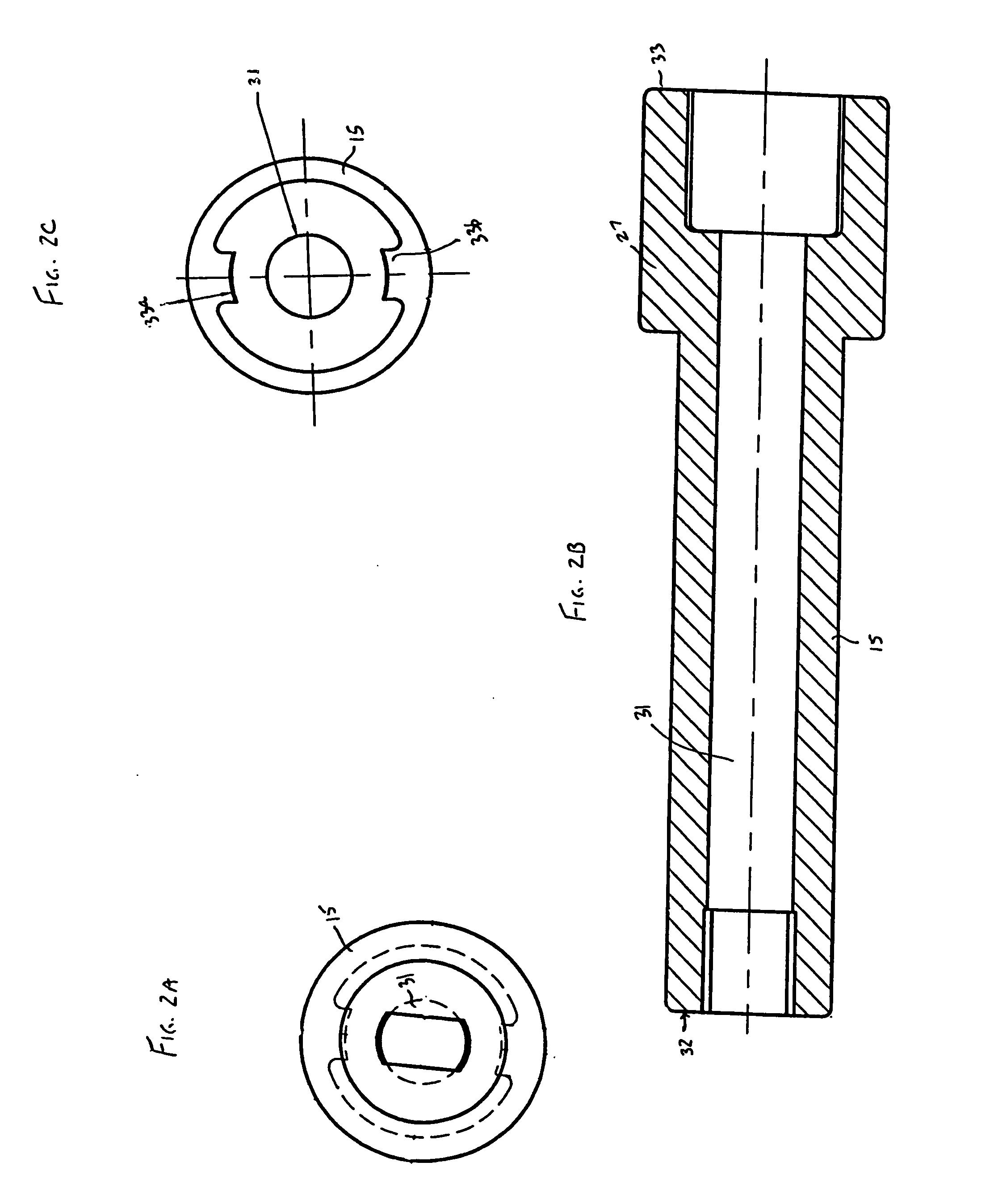
[0020] Turning to FIG. 1, the brake assembly of the present invention is shown. A rotatable hollow drum 10 is provided and is supported by supports 11A, 11B. Reversible motor 12 is mounted to the drum support 11A by any suitable means, such as one or more bolts 13. Those skilled in the art will know what types of motors are suitable for driving the drum in cable unwinding and winding directions, such motors generally including electric and hydraulic motors, with electric motors being particularly preferred. The motor includes a motor shaft 14 that extends into the cavity of the drum 10 as shown. Preferably the shaft is centrally located in the drum cavity. A brake drive coupling 15 is coupled to the motor shaft 14. With reference to FIGS. 2A, 2B and 2C, the brake drive coupling 15 is cylindrical, with the coupling body having a constant outer diameter except at a distal end 33 thereof which is substantially C-shaped and has a larger outer diameter as shown. The coupling 15 has a cen...


PUM


Abstract

Braking mechanism and a winch having the braking mechanism. The braking mechanism allows a winch with which it is associated to hold a load once the winch has dragged the load up an incline. The winch includes a motor, a drive shaft selectively driven in opposite rotative directions by the motor, a gearbox, a rotatable drum and a cable wrapped around the drum. The motor provides torque, which through the gearbox turns the drum of the winch. When the motor is stopped, and the load on the cable attempts to pull the cable back off the winch drum, the torque that is fed back from the drum into the gearbox and into the drive shaft engages the brake.

Description

BACKGROUND OF THF INVENTION [0001] The present invention is directed to a braking mechanism. More specifically, this invention relates to a braking mechanism having particular application in winches, especially in winches used for paying out cables and which are required to stop and maintain a load in place after the winching operation is completed. [0002] Utility winches generally must be capable of maintaining a load in place after the winching operation is completed, such as after a load is dragged up an incline. To that end, conventional winches incorporate a brake, which is engaged as a result of the load on the winch when the motor driving the winch is stopped. For example, U.S. Pat. No. Re. 36,216 discloses an automatic brake for a winch. The '216 patent relates to a brake mechanism for a winch for controlling the unwinding play out of the winch cable when subject to a load. Brake pads are positioned to radially expand against the inner wall of the drum. A fixed and an axiall...

Claims


Application Information

Patent Timeline
IPC IPC(8): B66D5/00B66D5/22
CPCB66D5/22
Inventor PETERSON, SCOTT
Owner SUPERWINCH
Why Eureka
Try Eureka