Miniature radio frequency transceiver

a radio frequency transceiver and miniature technology, applied in the direction of mechanical actuation of burglar alarms, instruments, using reradiation, etc., can solve the problems of limited data handling capability, large amount of power to operate, inefficient operation, etc., and achieve a high and sophisticated degree of rf communication capability, increase the overall size and volume of stamps or labels

Inactive Publication Date: 2005-11-03
ROUND ROCK RES LLC
View PDF99 Cites 9 Cited by
  • Summary
  • Abstract
  • Description
  • Claims
  • Application Information

AI Technical Summary

Benefits of technology

[0010] A further object of this invention is to provide a new and improved electronically powered postage stamp or mailing label of the type described including RFID integrated circuitry which is operatively powere...

Problems solved by technology

These reflective passive RFID packages operate by modulating the impedance of an antenna, but are generally inefficient in operation, require large amounts of power to operate, and ha...

Method used


Image

  • Miniature radio frequency transceiver
  • Miniature radio frequency transceiver
  • Miniature radio frequency transceiver

Examples


Embodiment Construction

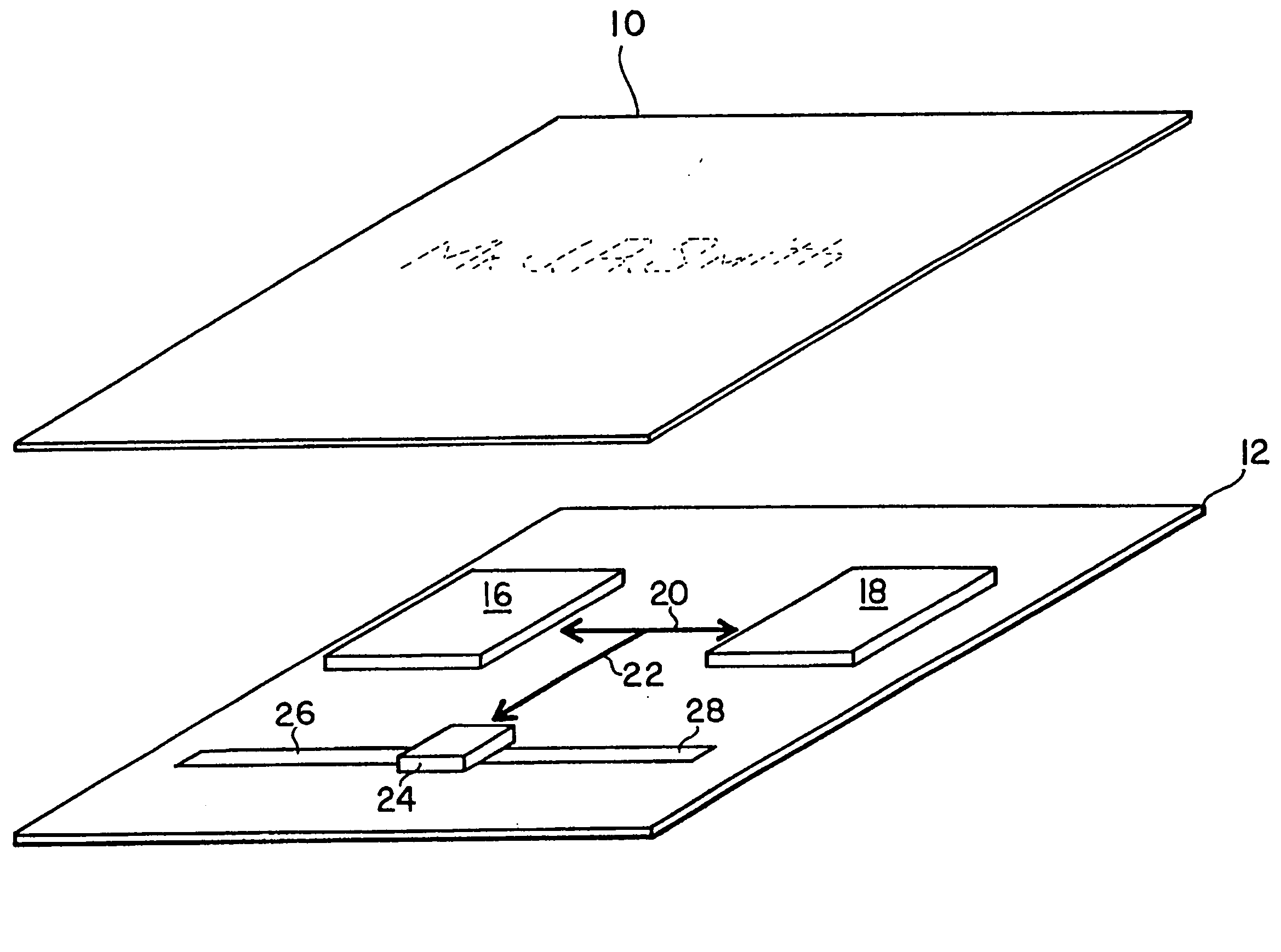
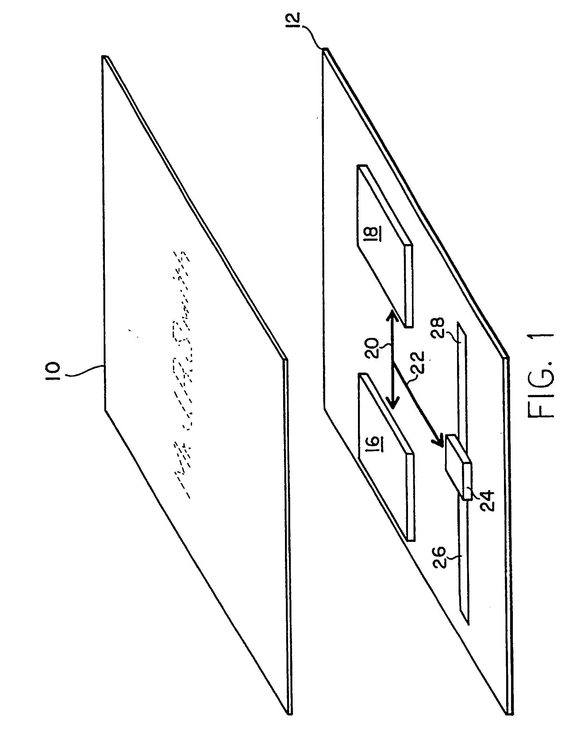
[0018] Referring now to FIG. 1, the electrically powered, RF operative label or stamp includes a cover member 10 and a base member 12 upon which a radio frequency identification system has been constructed using thin film deposition techniques of the type described in my above identified co-pending application Ser. No. (71-579) filed Jun. 17, 1992. Functionally speaking, the RFID system 14 will include one or more thin flat battery cells 16 and 18 which are connected in series as indicated by line 20 and are both connected via line 22 to drive an integrated circuit transceiver chip 24. The IC transceiver chip 24 will preferably be connected to a dipole antenna consisting of thin film antenna strips 26 and 28, and the dipole antenna 26 and 28 is operative to both transmit RF signals from the IC chip 24 to a controller and to receive incoming RF signals from an external RF source controller and operative to encode this data in IC chip memory in a manner more particularly described bel...


PUM


Abstract

The present application describes an electronically powered postage stamp or mailing label and including a radio frequency identification (RFID) device and system mounted between the opposing and facing major surfaces thereof. The RFID device and system includes an integrated circuit transceiver chip which is connected to and powered by a thin flat battery cell and is operated with a thin film RF antenna, all of which are mounted in side-by-side relationship on a thin base or support layer. These thin flat components are mounted in an essentially two dimensional planar configuration well suited for incorporation into the planar structure of a postage stamp or a mailing label. In addition, the RFID transceiver chip may be replaced with an electro-optically operated IC chip using, for example, LEDs or laser diodes for the propagation of light signals to an interrogator.

Description

[0001] This application is a continuation of application Ser. No. 09 / 481,807 filed Jan. 11, 2000, which is a divisional of application Ser No. 08 / 934,701 filed Sep. 22, 1997, now U.S. Pat. No. 6,013,949; which is a continuation of application Ser. No. 08 / 610,236 filed Mar. 4, 1996, now abandoned; which is a continuation of application Ser. No. 08 / 168,909 filed Dec. 17, 1993, now U.S. Pat. No. 5,497,140; which is a continuation of application Ser. No. 07 / 928,899 filed Aug. 12, 1992, now abandoned.TECHNICAL FLED [0002] This invention relates generally to electrically powered postage stamps and mailing labels which operate to transmit radio frequency (RF) identification signals to an interrogator either at the point of shipment origin, in transit, or upon reaching a point of destination. More particularly, this invention relates to such stamps and labels having an integrated circuit therein powered by a thin flat battery cell. RELATED APPLICATION AND BACKGROUND ART [0003] In my co-pend...

Claims


Application Information

Patent Timeline
IPC IPC(8): G01S13/75G01S13/76G06K19/07G06K19/073G06K19/077G07B17/00G08B13/14H04L29/12
CPCG01S13/758H04L61/6022G06K19/0702G06K19/0723G06K19/0728G06K19/073G06K19/07749G06K19/07758G06K19/0776G06K19/07786G07B2017/00629H04L29/12254H04L29/12264H04L29/12311H04L29/12801H04L29/12839H04L61/2038H04L61/2046H04L61/2084H04L61/6004G01S13/767H04L61/5046H04L61/5038H04L61/5084H04L2101/604H04L2101/622
Inventor TUTTLE, JOHN R.
Owner ROUND ROCK RES LLC
Why Eureka
Try Eureka