Low profile hybrid phased array antenna system configuration and element

a phased array, low-profile technology, applied in the direction of antennas, radiating elements, electrical equipment, etc., can solve the problems of cumbersome existing dish technology, large patch size, and inability to use on a vehicl

Inactive Publication Date: 2005-11-03
INTELWAVES TECH
View PDF11 Cites 63 Cited by
  • Summary
  • Abstract
  • Description
  • Claims
  • Application Information

AI Technical Summary

Benefits of technology

[0006] It is an object of the present invention to obviate or mitigate at least one disadvantage of previous antenna elements and arrays.

Problems solved by technology

Existing dish technologies are cumbersome and not suitable for use on a vehicle.
However, a drawback is that a large patch size is typically required in order to obtain a high gain, i.e. the gain of the system is about a 30 to 32 decibel gain, in order to properly receive satellite signals.

Method used


Image

  • Low profile hybrid phased array antenna system configuration and element
  • Low profile hybrid phased array antenna system configuration and element
  • Low profile hybrid phased array antenna system configuration and element

Examples


Embodiment Construction

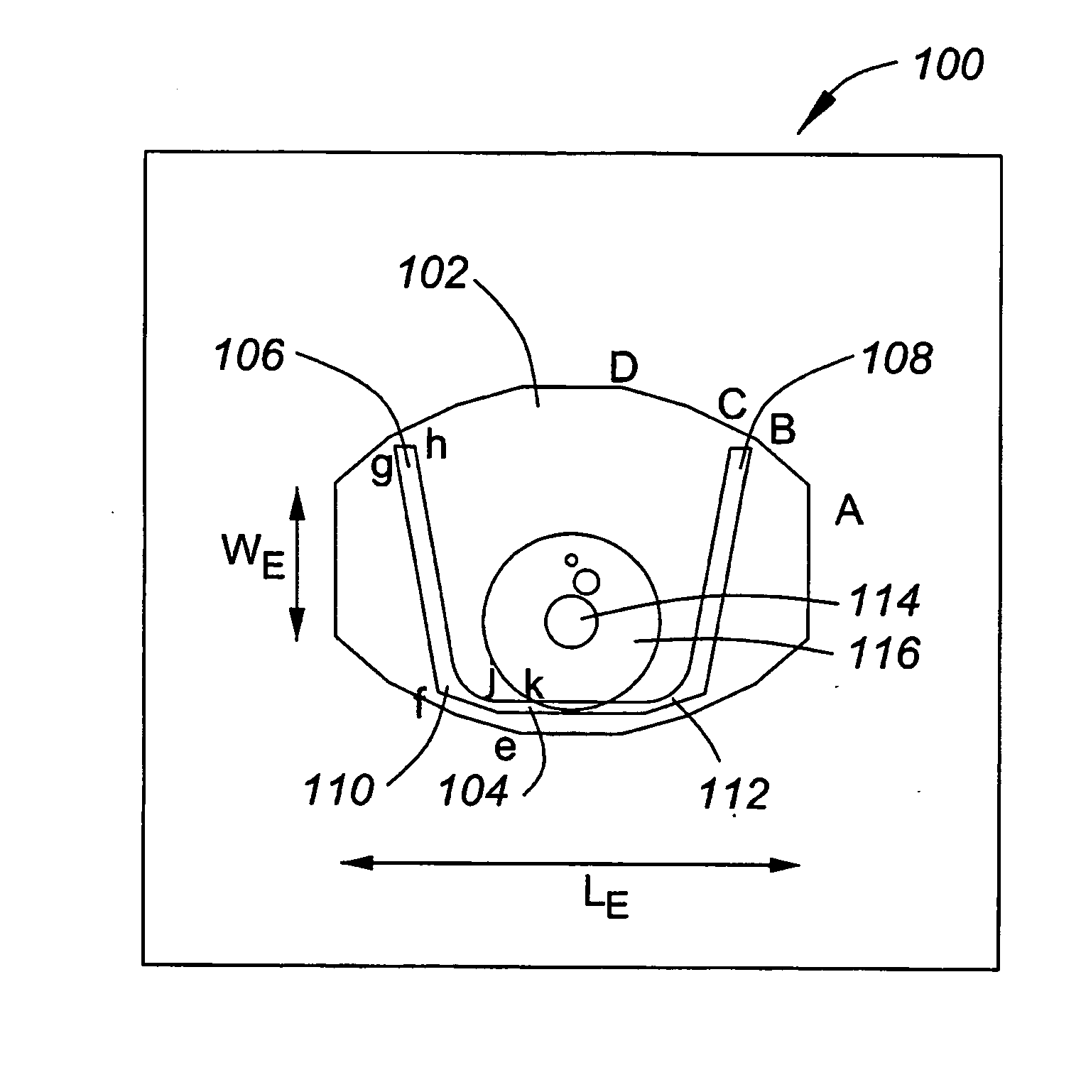
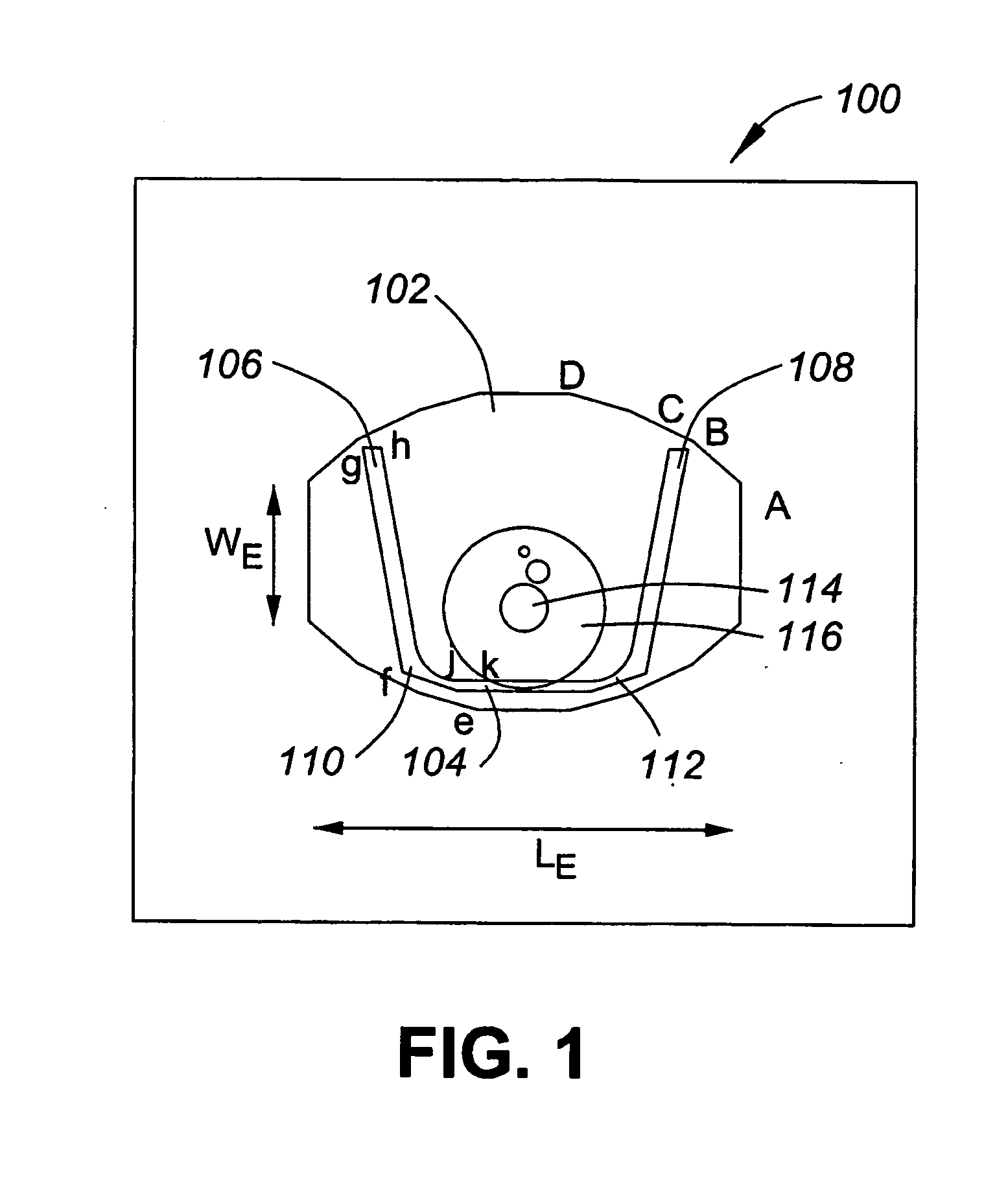
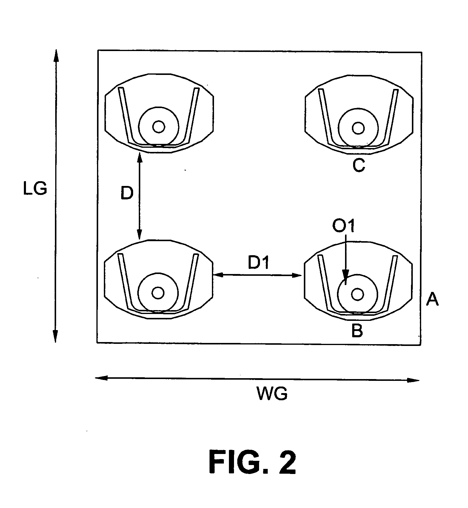
[0038] Generally, the present invention provides a microstrip patch antenna having a high gain performance with a smaller size compared to existing approaches. An antenna according to an embodiment of the present invention includes a patch having a polygon shape and a modified V-slot in the polygon patch including high-frequency control segments. Such an antenna has a dual band performance, such as in the Ka and Ku bands. While some known approaches use a V-slot on a rectangular patch, such known approaches only provide a wideband response and are not able to provide a dual band performance. An array of antenna elements is also described, as well as an ultra low profile phased array antenna system.

[0039] The term “high gain” as used herein in relation to an antenna represents an antenna that significantly increases signal strength. High-gain antennas are necessary for long-range wireless networks, and for satellite networks. A high gain antenna is highly focused, whereas a low gain...


PUM


Abstract

A microstrip patch antenna is provided having a high gain performance with a smaller size compared to existing approaches. The antenna includes a patch having a polygon shape, such as a convex polygon, and a modified V-slot in the polygon patch including high-frequency control segments. Such an antenna has a dual band performance, such as in the Ka and Ku bands. An array of antenna elements is also described, as well as an ultra low profile phased array antenna system.

Description

CROSS REFERENCE TO RELATED APPLICATIONS [0001] This application claims the benefit of priority of U.S. Provisional Patent Application No. 60 / 565,515 filed Apr. 27, 2004, which is incorporated herein by reference.FIELD OF THE INVENTION [0002] The present invention relates generally to antenna elements used for receiving and transmitting data signals, such as from or to a satellite. The present invention also relates to an array of such antenna elements, as well as a system incorporating a plurality of such arrays. BACKGROUND OF THE INVENTION [0003] Satellite transmission is used for a variety of applications, such as for transmitting television signals, also known as direct broadcast system (DBS) signals. Many arrangements exist for receiving such satellite signals at a home, or at another fixed location. There is a need to be able to receive such signals in a mobile environment, such as in a vehicle. Existing dish technologies are cumbersome and not suitable for use on a vehicle. So...

Claims


Application Information

Patent Timeline
Patent Type & Authority Applications(United States)
IPC IPC(8): H01Q1/38H01Q5/00H01Q5/357H01Q9/04H01Q13/08H01Q13/10H01Q21/06
CPCH01Q9/0442H01Q5/357H01Q21/065
Inventor RAFI, GHOLAMREZAALAMDARI, IRAJ EHTEZAZIBAFROOEI, PEDRAM MOUSAVISAFAVI-NAEINI, SAFEIDDINKAHRIZI, MASOUD
Owner INTELWAVES TECH
Why Eureka
Try Eureka