
Ink jet head substrate, ink jet head and method of manufacturing ink jet head substrate

a technology which is applied in the field substrate manufacturing method of can solve the problems of unstably operated thermal ink jet recording device, limit in reducing heat-generating resistor area, etc., and achieve enhanced thermal/mechanical endurance and high resistivity

Inactive Publication Date: 2005-11-03
S PRINTING SOLUTION CO LTD
View PDF6 Cites 4 Cited by
  • Summary
  • Abstract
  • Description
  • Claims
  • Application Information

AI Technical Summary

Benefits of technology

[0012] In order to solve the foregoing and / or other problems, it is an aspect of the present general inventive concept to provide an ink jet head substrate with a heat-generating resistor having a high resistivity and an enhanced thermal / mechanical endurance.

Problems solved by technology

Thus, there is a limitation in reducing the area of the heat-generating resistor.
In order to increase the sheet resistance of the heat-generating resistor, there has been proposed a method of reducing a thickness of the heat-generating resistor, but this method causes the resistance to vary remarkably as the energy applied to the heat-generating resistor is increased, thereby causing the thermal ink jet recording device to be unstably operated.

Method used


Image

  • Ink jet head substrate, ink jet head and method of manufacturing ink jet head substrate
  • Ink jet head substrate, ink jet head and method of manufacturing ink jet head substrate
  • Ink jet head substrate, ink jet head and method of manufacturing ink jet head substrate

Examples


Embodiment Construction

[0032] Reference will now be made in detail to the embodiments of the present general inventive concept, examples of which are illustrated in the accompanying drawings, wherein like reference numerals refer to the like elements throughout. The embodiments are described below in order to explain the present general inventive concept by referring to the figures. In the drawings, the thickness of layers and regions are exaggerated for clarity. Like numbers refer to like elements throughout the specification.

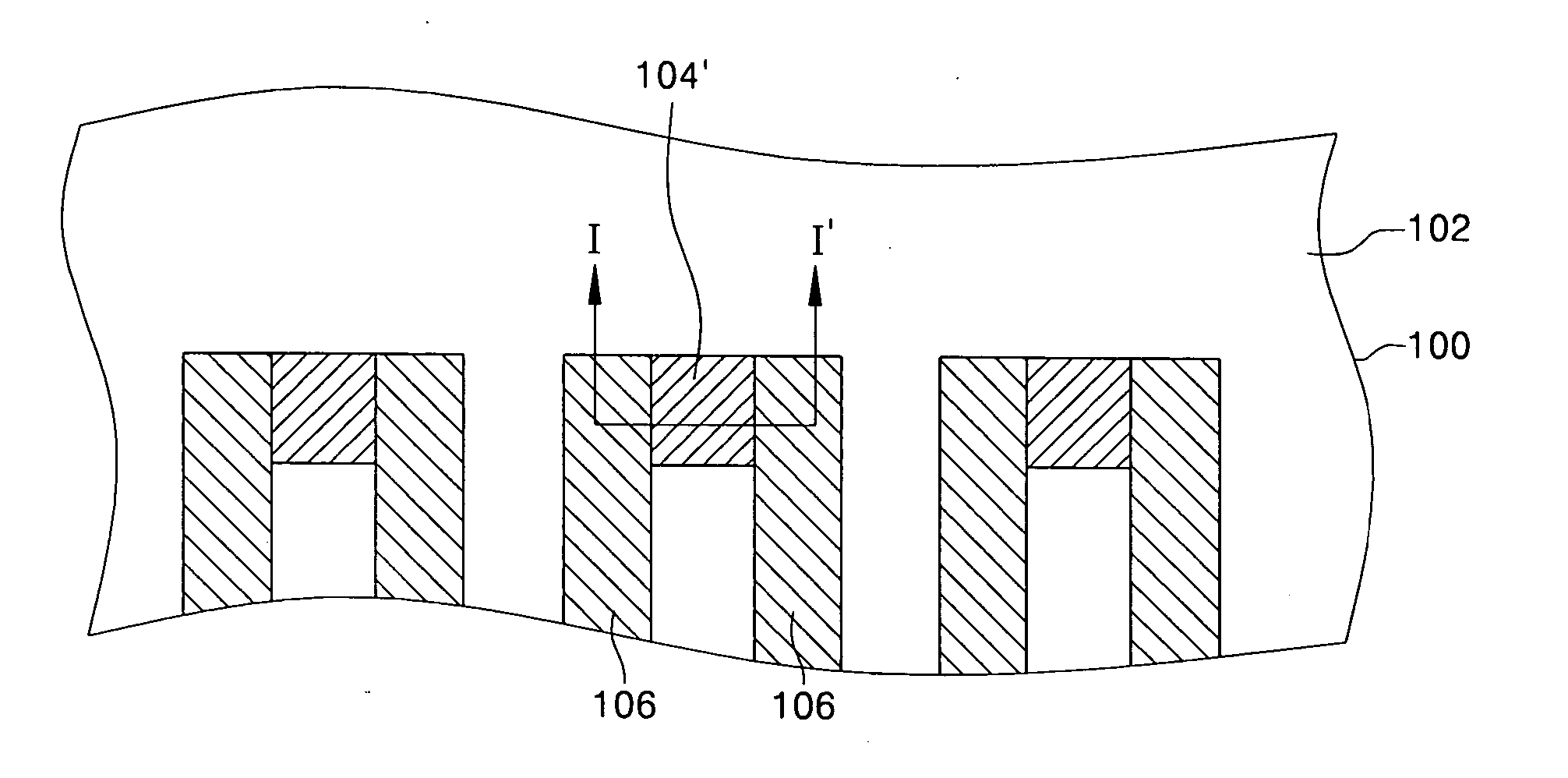
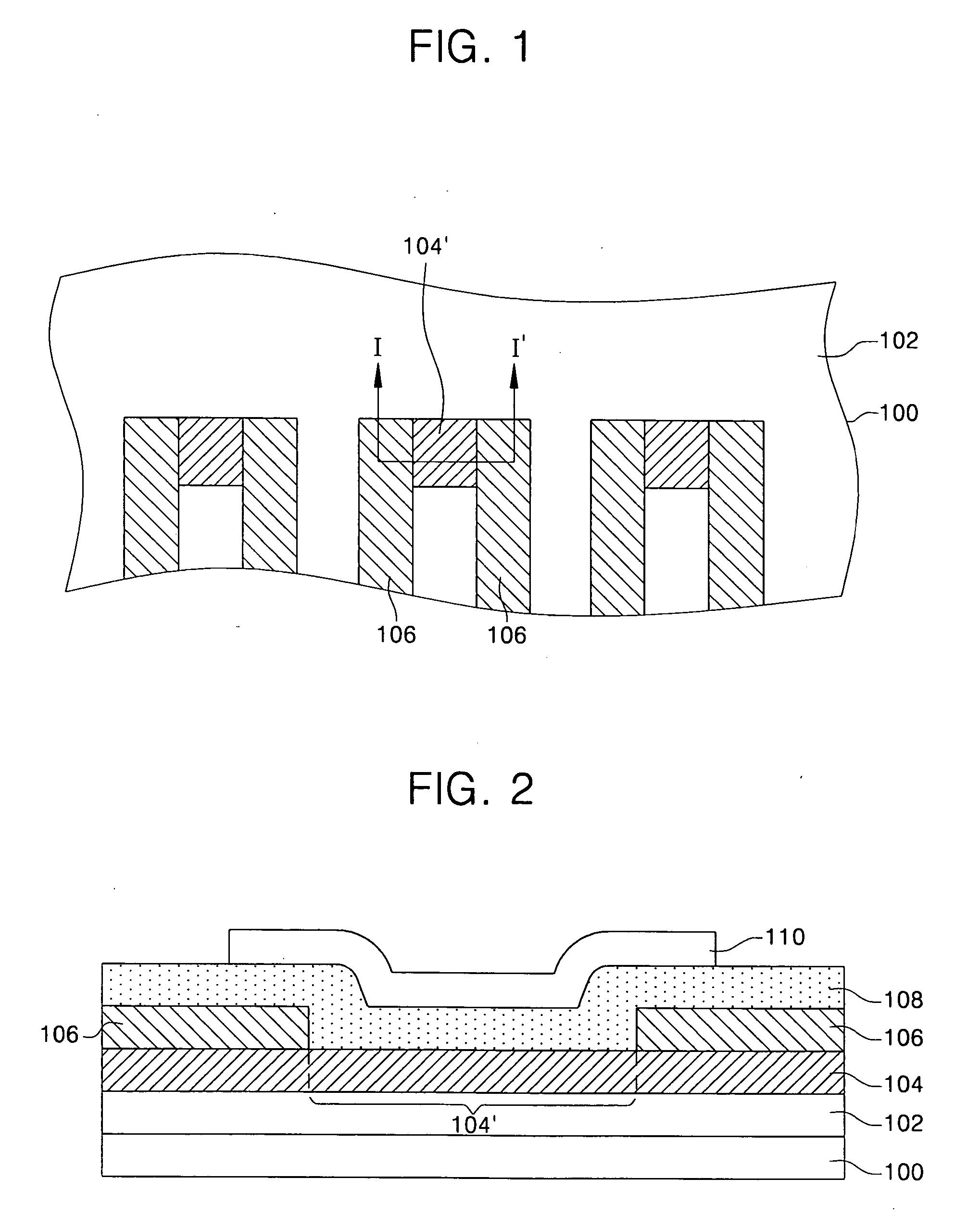
[0033]FIG. 1 is a partial plan view illustrating an ink jet head substrate used with an ink jet head and a thermal ink jet recording device according to an embodiment of the present general inventive concept, and FIG. 2 is a cross-sectional view taken along a line I-I′ of FIG. 1.

[0034] Referring to FIGS. 1 and 2, a heat-generating resistive layer pattern 104 can be disposed on a supporting structure 100. A heat-generating resistor 104′ can occupy a predetermined area of the heat-g...


PUM


Abstract

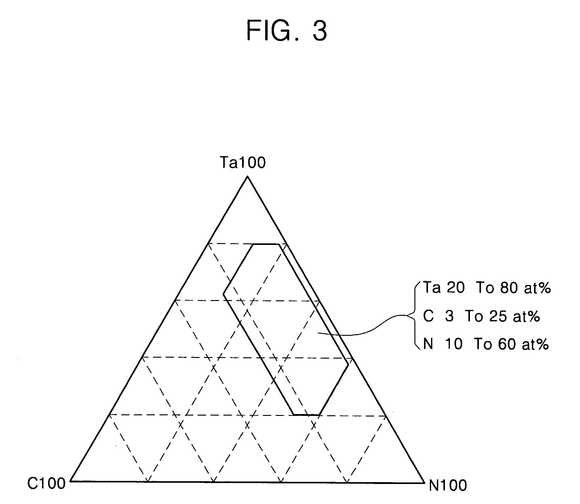
An ink jet head substrate, an ink jet head and method of manufacturing the ink jet head substrate. The ink jet head substrate includes a supporting structure and at least one heat-generating resistor disposed on the supporting structure to generate a thermal energy to eject ink and made of metal carbon nitride. The metal carbon nitride is represented as a chemical formula of MxCyNz where M is metal, X is within about 20 through 80, Y is within about 3 through 25, and Z is within about 10 through 60, when X+Y+Z=100. Further, the heat-generating resistor has a resistivity of 300˜2000 μΩ·Cm.

Description

CROSS-REFERENCE TO RELATED APPLICATIONS [0001] This application claims the benefit of Korea Patent Application No. 2004-16598 filed on Mar. 11, 2004, the disclosure of which is hereby incorporated herein by reference in its entirety. BACKGROUND OF THE INVENTION [0002] 1. Field of the Invention [0003] The present general inventive concept relates to an ink jet head substrate, an ink jet head and method of manufacturing the ink jet head substrate and, more particularly, to an ink jet head substrate provided with a heat-generating resistor having an enhanced reliability and an expanded life span, an ink jet head having the ink jet head substrate, and method of manufacturing the ink jet head substrate. [0004] 2. Description of the Related Art [0005] An ink jet recording device is a device for printing a picture by ejecting a minute droplet of printing ink to a desired position of a recording medium. Such an ink jet recording device is widely used because a price thereof is relatively lo...

Claims


Application Information

Patent Timeline
IPC IPC(8): B41J2/14B41J2/05B41J2/16
CPCB41J2/14129B41J2/1412A22C25/22A22C25/08A22C25/003
Inventor MIN, JAE-SIKPARK, SUNG-JOONHA, YOUNG-UNG
Owner S PRINTING SOLUTION CO LTD
Learn More