Light-emitting apparatus

a light-emitting apparatus and light-emitting technology, which is applied in the direction of lighting and heating apparatus, fixed installation, instruments, etc., can solve the problems of complex structure of light-emitting apparatus, inability to change the angle or focus position of light emitted from the convex lens,

Inactive Publication Date: 2005-11-03
CITIZEN ELECTRONICS CO LTD
View PDF3 Cites 58 Cited by
  • Summary
  • Abstract
  • Description
  • Claims
  • Application Information

AI Technical Summary

Benefits of technology

[0010] An object of the present invention is to provide a light-emitting apparatus capable of changing a focal position of light emitted from a light-emitting source by applying a current to a liquid crystal lens in order to illuminate various objects having different sizes or disposed in different distances efficiently.

Problems solved by technology

However, because each of the conventional light-emitting apparatuses as described above uses the normal convex lens 3 having a fixed focal length, an angle or focusing position of light emitted from the convex lens cannot be changed.
In order to achieve the change for the focal length, directions of emitted light, and the illuminating area a mechanism must be provided to move a focal length of one lens or at least one lens of the plurality of lenses relative to the light-emitting source, there is a problem that the light-emitting apparatus has a complicated structure.

Method used


Image

  • Light-emitting apparatus
  • Light-emitting apparatus
  • Light-emitting apparatus

Examples


first embodiment

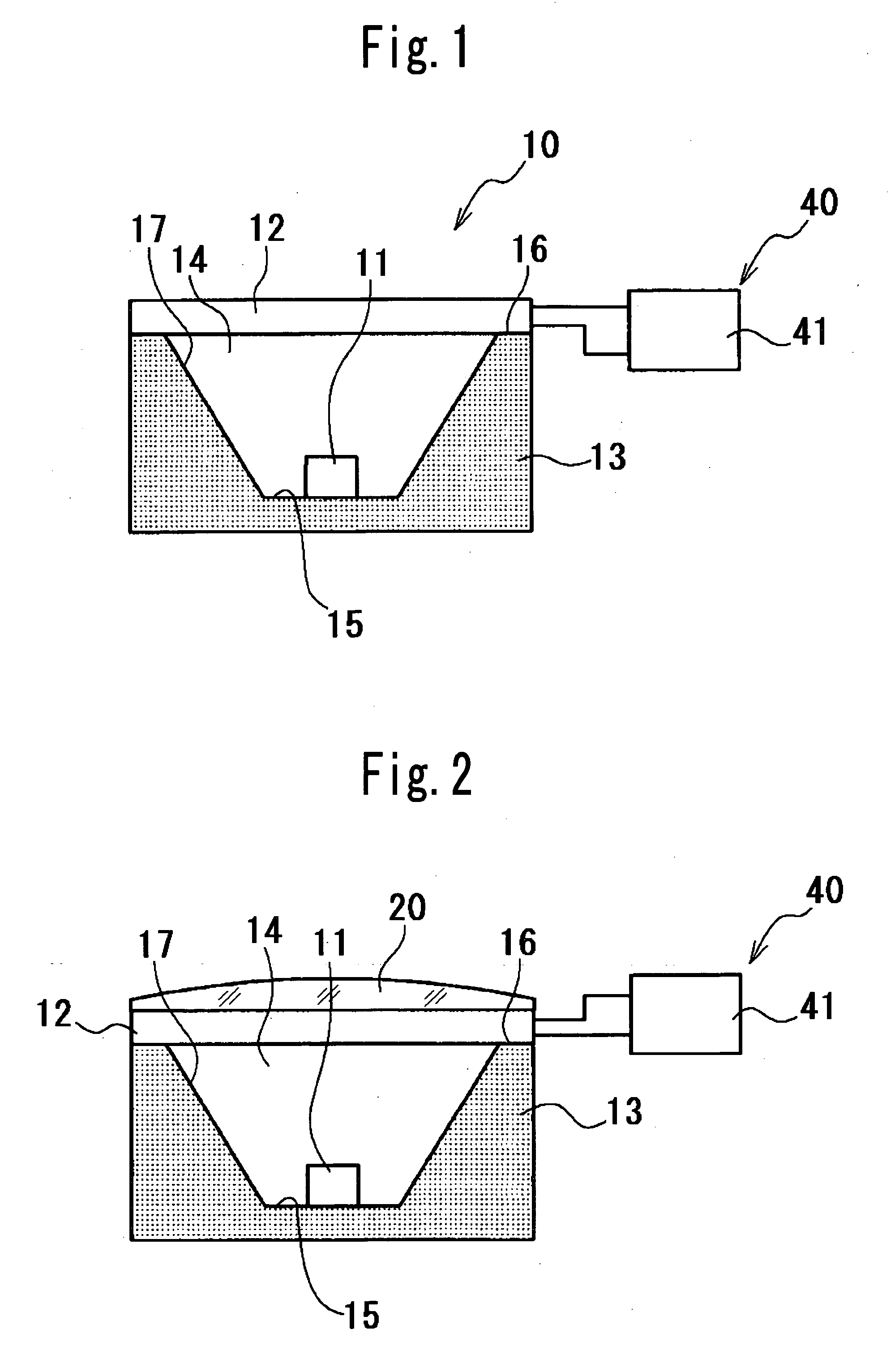
[0025] Referring to FIG. 1, a first embodiment showing a basic structure of a light-emitting apparatus according to the present invention is illustrated.

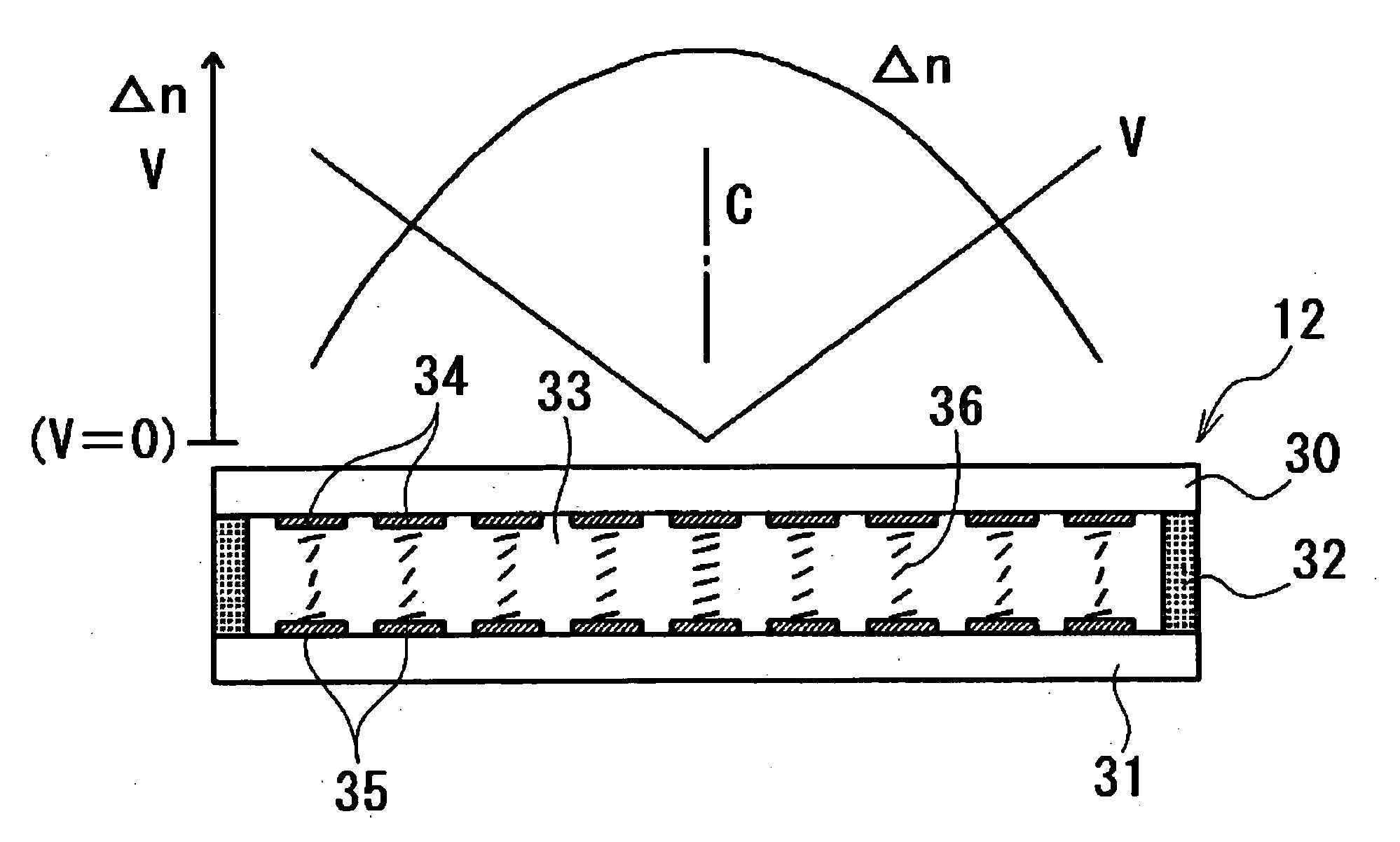
[0026] The light-emitting apparatus 10 in the first embodiment comprises at least one LED element, and at least one liquid crystal lens disposed to face the LED element and spaced from the LED element.

[0027] If the light-emitting apparatus according to the present invention is used for a flashlight of a camera, interior lightings, and spotlights, Red-Green-Blue (RGB)-color LED elements or a combination of white LED comprising a blue LED element and fluorescent material(s) and a red LED may be used for color rendering properties.

[0028] LED element(s) used in the embodiments of the present invention may be covered by a translucent resin containing fluorescent material(s). The translucent resin may also contain dye compound(s).

[0029] If the light-emitting apparatus according to the present invention is used for a flashlight of a cam...

second embodiment

[0036] Referring to FIG. 2, the light-emitting apparatus according to the present invention is illustrated.

[0037] The light-emitting apparatus in the second embodiment includes at least one lens 20 placed on the liquid crystal lens 12, other structure is the same as in the first embodiment. In the second embodiment, a normal convex lens is used as the lens 20. However, a concave lens may be used.

[0038] With the structure shown in the second embodiment, a variable range of the focal length of the liquid crystal lens 12 is compensated with the normal lens 20, a control scope for a focusing position by a voltage is corrected to a long and short distance, and the light-emitting apparatus can be applied in a wider scope of use. Here, the liquid crystal lens 12 can be used to have focusing property or dispersing property. Either the liquid crystal lens 12 or the normal lens 20 may be disposed to face the LED element 11.

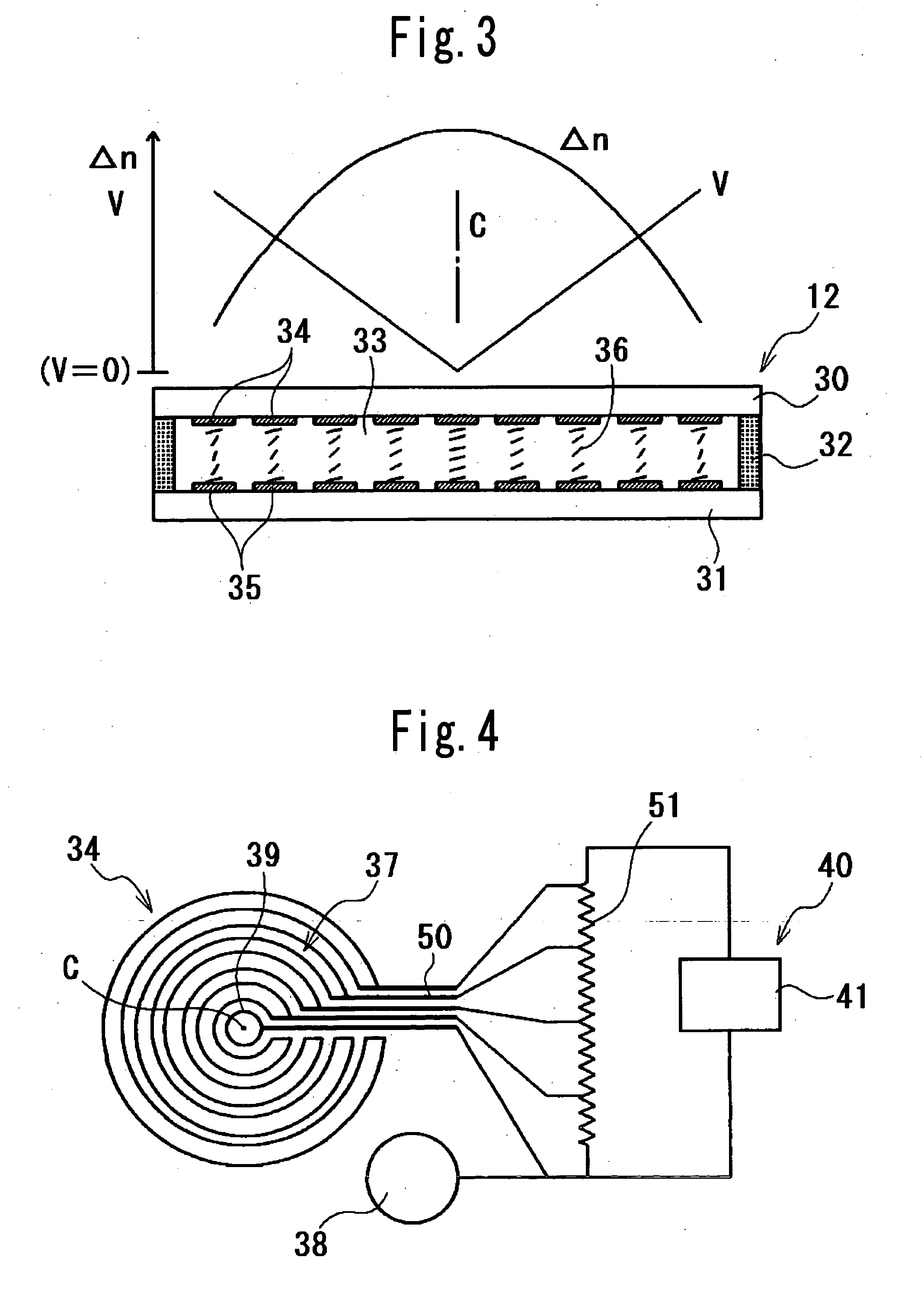
[0039] The controlling device 40 includes a variable voltage source ...


PUM

PropertyMeasurementUnit
distanceaaaaaaaaaa
voltageaaaaaaaaaa
transparentaaaaaaaaaa

Abstract

A light-emitting apparatus, comprising at least one LED element, and at least one liquid crystal lens disposed to face the LED element and positioned at a distance from the LED element, a focal length of light, broadening and narrowing directions of light, and changing the illuminating area of light being adjustable by applying a voltage to the at least one liquid crystal lens and a light-emitting apparatus, further comprising at least one lens placed on the liquid crystal lens.

Description

CROSS-REFERENCE TO THE RELATED APPLICATION [0001] The application claims the priority benefit of Japanese Patent Application No. 2004-136755, filed on Apr. 30, 2004, the entire descriptions of which are incorporated herein by reference. BACKGROUND OF THE INVENTION [0002] 1. Field of the Invention [0003] The present invention relates to a light-emitting apparatus, more specifically to a light-emitting apparatus in which a focusing position of light emitted from a light-emitting source, broadening and narrowing directions of emitted light, and changing the illuminating area are electrically controlled. [0004] 2. Description of Related Art [0005] There is generally known that a light-emitting apparatus includes a light-emitting source such as a light-emitting diode (LED) element, a filament lamp or the like, and a convex lens disposed in front of an emission surface of the light-emitting source, and the convex lens works to focus light emitted from the emission surface of the light-emi...

Claims


Application Information

Patent Timeline
Patent Type & Authority Applications(United States)
IPC IPC(8): F21S8/10G02F1/13F21V5/04F21V14/00F21V17/00F21V17/02F21Y101/02G02F1/1335G02F1/1343G02F1/29H01L33/48H01L33/58H01L33/60H01L33/62
CPCF21S48/10F21S48/1731F21V14/003G02F2203/28G02F1/134309G02F1/29G02F2001/294F21Y2101/02F21Y2115/10F21S41/645G02F1/294F21S41/141F21S41/25F21S41/143F21S43/14F21S41/285F21S41/00
Inventor SASUGA, MASATOSHI
Owner CITIZEN ELECTRONICS CO LTD
Why Eureka
Try Eureka