Multiple level transmitter and method of transmitting

a multi-level transmitter and transmitter technology, applied in the direction of pulse train generators, mechanical vibration separation, instruments, etc., can solve the problem of limited control of the transmit energy spectrum

Inactive Publication Date: 2005-11-03
PETERSEN DAVID A +1
View PDF14 Cites 2 Cited by
  • Summary
  • Abstract
  • Description
  • Claims
  • Application Information

AI Technical Summary

Benefits of technology

[0008] Further aspects and advantages of the invention are discussed below in conjunction with the preferred embodiments.

Problems solved by technology

Simple switching pulsers avoid dissipation associated with linear output amplifiers, but provide limited control of the transmit energy spectrum.

Method used


Image

  • Multiple level transmitter and method of transmitting
  • Multiple level transmitter and method of transmitting
  • Multiple level transmitter and method of transmitting

Examples


Embodiment Construction

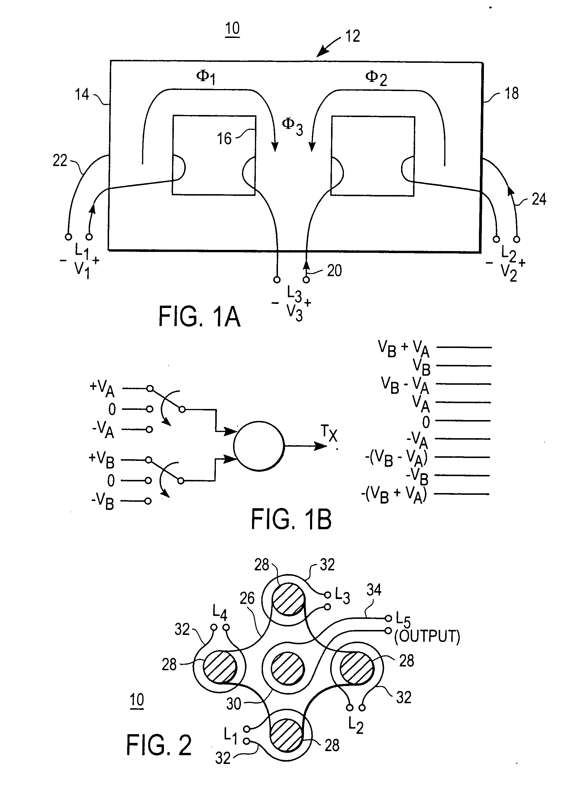
[0018] A multilevel transmit waveform or pulse, such as a waveform with three, four or more non-zero amplitudes, is generated by superposition of a plurality of input voltages. In one embodiment, a transformer with three or more magnetic flux paths superposes magnetic flux in one of the paths from the plurality of other paths. In another embodiment, voltages generated at secondary windings of a plurality of transformers connected in series are summed. The superposition of either embodiment provides a multilevel output transmit waveform.

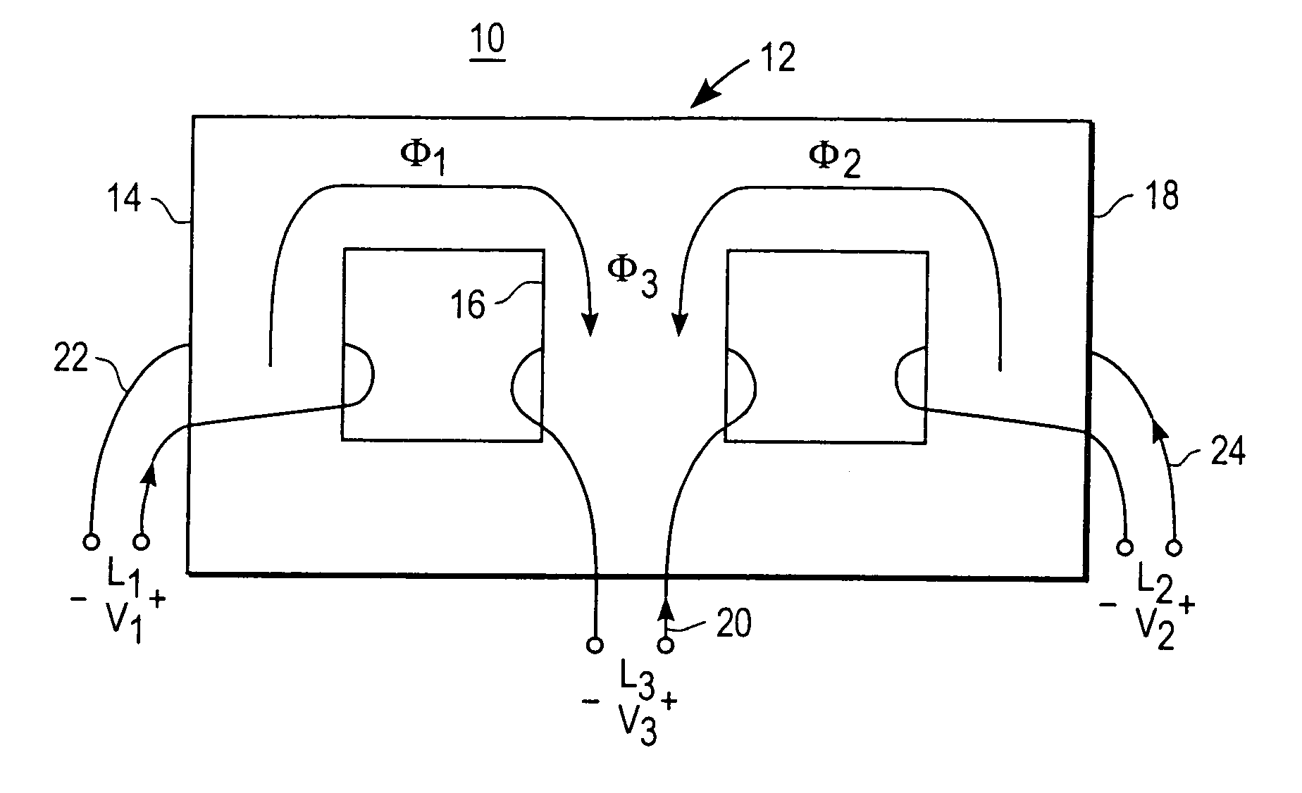
[0019]FIG. 1A shows a transformer of one embodiment for superposing magnetic flux. To generate a transmit pulse in response to a fixed set of input levels, the transformer 10 includes a ferrite core 12 with three or more separate flux paths 14, 16, 18, a secondary winding 20, and primary windings 22 and 24. Additional, different or fewer windings and flux paths may be provided.

[0020] The core 12 comprises a ferrite core or other magnetic core materi...


PUM


Abstract

Transmitters for generating multilevel transmit waveforms for medical diagnostic ultrasound are provided. Voltages from a plurality of sources are superposed or summed. Switches control the amplitude and polarity of the summed voltages so that a transmit waveform having four or more, such as nine, voltage levels is provided. A simple switching pulser without a power amplifier combines voltages applied to two or more flux paths in a third flux path. Superposition of magnetic flux in the third flux path provides for an output voltage responsive to the sum and difference of two different voltages. Alternatively or additionally, the secondary windings of multiple transformers are connected in series with a transducer element. By providing different input voltages to each of the transformers, the multilevel transmit waveform is generated.

Description

BACKGROUND [0001] The present invention relates to generating waveforms. In particular, the invention relates to a transmit and receive circuit for an ultrasound system. [0002] Short, high-energy transmit waveforms drive ultrasound transducers for diagnostic medical imaging. The transmit waveforms are generated by switching pulsers. Simple switching pulsers avoid dissipation associated with linear output amplifiers, but provide limited control of the transmit energy spectrum. For example, simple bipolar or unipolar waveforms are generated. [0003] U.S. Pat. Nos. 6,083,164 and 6,050,945 disclose transmit and receive circuitry using switching pulsers. FIG. 14 of U.S. Pat. No. 6,083,164 discloses two switches S1, S2 connected to primary windings with a voltage source. The secondary winding of the transformer achieves a positive or negative voltage value for generating a bipolar waveform at the transducer element. With an extra primary winding, associated switches and different source vo...

Claims


Application Information

Patent Timeline
Patent Type & Authority Applications(United States)
IPC IPC(8): B06B1/02A61B8/00B06B3/00B06B3/04G03B42/06H04B1/02H04L5/04H04L25/49H04R17/00
CPCH04L25/4917H04L5/04
Inventor PETERSEN, DAVID A.PHELPS, ROBERT N.
Owner PETERSEN DAVID A
Why Eureka
Try Eureka