Automatic tolerance determination system for material application inspection operation

a technology of tolerance determination and material application, applied in the direction of spraying apparatus, metallic material coating process, chemical vapor deposition coating, etc., can solve the problems of product waste and time, and achieve the effect of less substrate was

Inactive Publication Date: 2005-11-03
NORDSON CORP
View PDF20 Cites 25 Cited by
  • Summary
  • Abstract
  • Description
  • Claims
  • Application Information

AI Technical Summary

Benefits of technology

[0016] The verification system of the present invention is easy to use, as well as easier to setup and maintain. The tolerance feedback feature of the present invention is especially useful in addressing those adhesive dispensing applications challenges that relate to changing application and equipment conditions. Therefore, the system increases yields and reduces scrap product and hence, reduces manufacturing costs and product unit cost.
[0017] Features of the present invention that automatically determine edge tolerance greatly reduce the complexity and inaccuracies associated with manually calculating the tolerances. Such tolerances are conventionally determined by trial and error, resulting in wasted product and time. Features of the invention also enhance robustness and reduce the number of false detections by virtue of their statistical foundation.
[0019] In terms of adhesive monitoring, features of the invention may track any pattern type, which may range from a single bead to any number of beads and bead configurations. Still other adhesive patterns verified by the processes of the present invention may include swirl patterns, other back and forth patterns, dots, film, atomized or sprayed applications, etc. Feedback features may further accommodate changes in variable line speed and other operating variables. Thus, the integration of verification and dispensing functions of the present invention improve efficiency, speed and accuracy. The system also requires less setup time than with conventional systems that require the tedious and continuous input of manually calculated tolerances.
[0020] In one respect, the system learns new tolerance limits after a change is made to a pattern. Namely, the system may automatically and concurrently learn a new pattern or other variation by conducting statistical analysis on sample data that embodies the change. The system thus accommodates various adhesive pattern types such as those produced by autospotting, which can change on-the-fly. Where an operator changes an adhesive pattern, e.g., changes the position of a leading bead edge from ten to twenty millimeters, the same statistics and / or previous tolerance determinations relating to the equipment may be reused, where applicable. Thus, the system avoids confusion, interruption and other efficiencies conventionally associated with adhesive pattern changes.
[0023] Embodiments consistent with the principles of the present invention have particular application when a conveyer changes speeds. That is, real time feedback mechanisms of the invention are particularly useful during stops and starts, when speed fluctuates greatly. In tracking the speed changes via the feedback loop, considerably less substrate is wasted than with conventional systems.

Problems solved by technology

Such tolerances are conventionally determined by trial and error, resulting in wasted product and time.

Method used


Image

  • Automatic tolerance determination system for material application inspection operation
  • Automatic tolerance determination system for material application inspection operation
  • Automatic tolerance determination system for material application inspection operation

Examples


Embodiment Construction

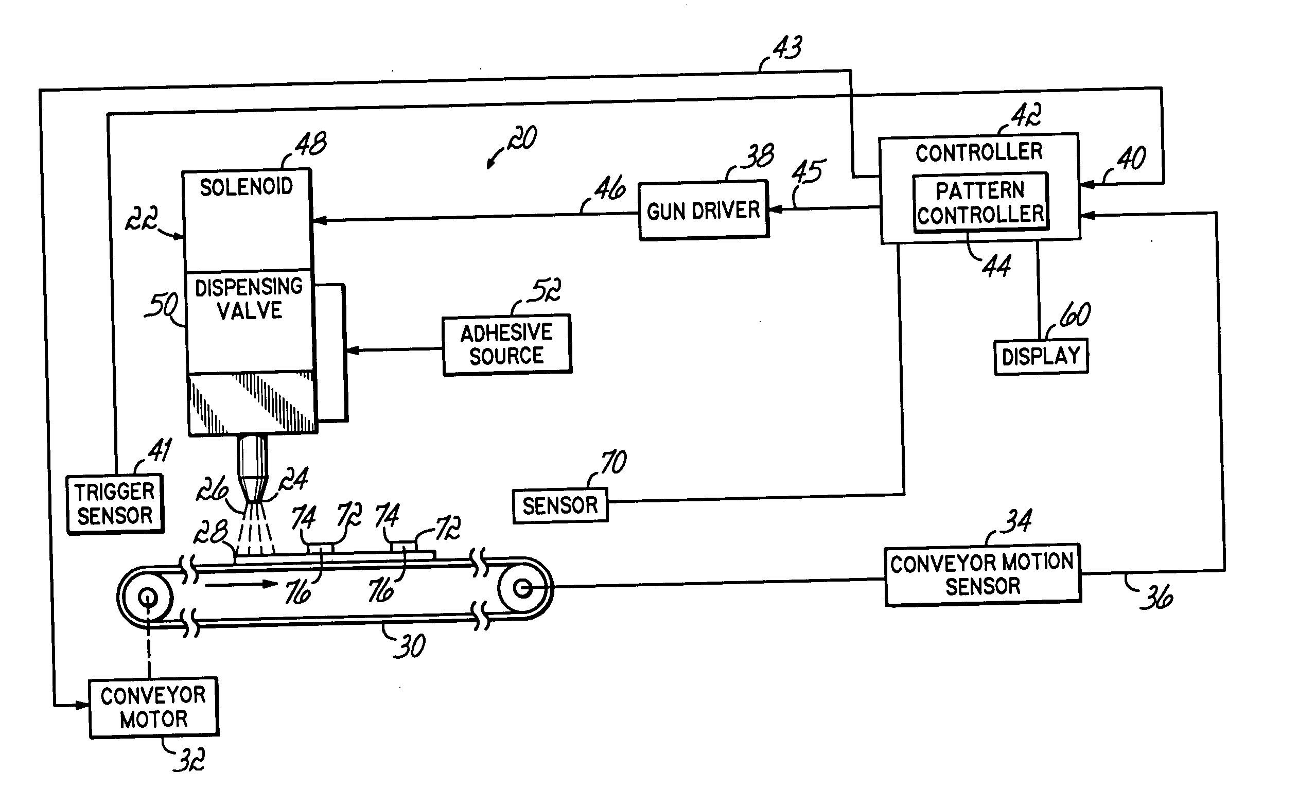
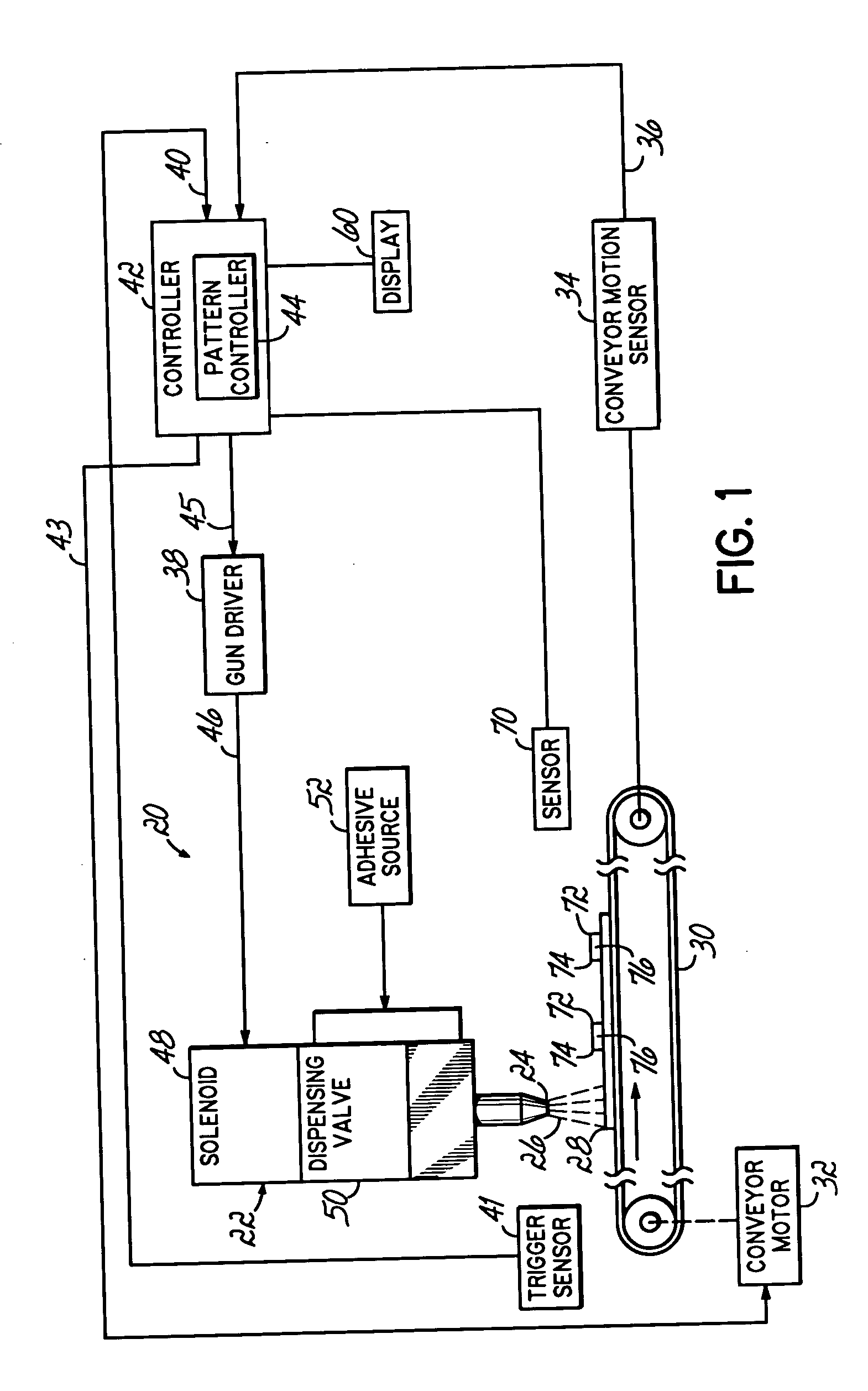
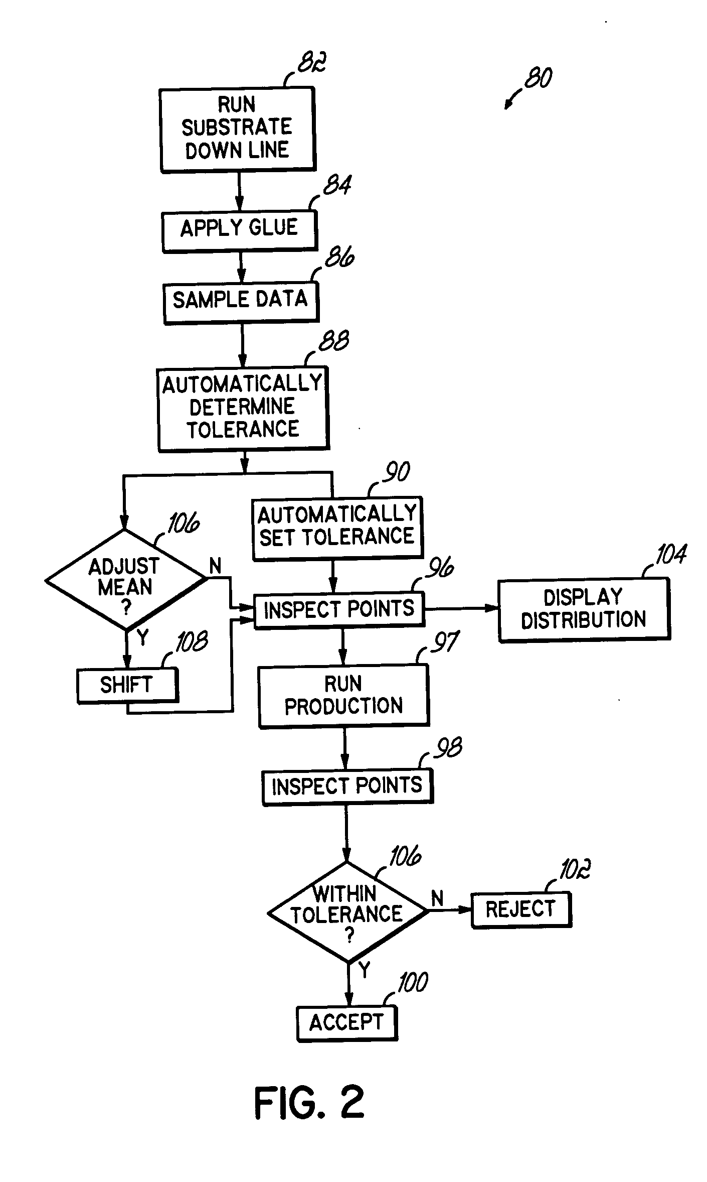
[0031] The various embodiments of the verification system of the present invention automatically determine and set a tolerance window to verify and monitor the accuracy of an adhesive application. The system typically analyzes statistical data to automatically determine respective tolerances at a number of inspection points. In one respect, the system may effectively “learn” a pattern from the data measurements and then compute respective reference locations, such as means, in addition to respective spreads, such as standard deviations, and ultimately, tolerances based on the learned pattern. The system then applies adhesive per application specifications and monitors the product result based on the new statistical tolerances. These tolerances are thus fed back in real time to track system hardware and adhesive pattern variances.

[0032] In one example, samples are gathered and a standard deviation or other spread is automatically computed. Other exemplary spreads may include an inte...


PUM

PropertyMeasurementUnit
lengthaaaaaaaaaa
widthaaaaaaaaaa
heightaaaaaaaaaa

Abstract

A method, apparatus and program product automatically determine and set a tolerance window to verify and monitor the accuracy of an adhesive application. Statistical data is processed concurrently to determine the tolerance at a given inspection point. The system then applies adhesive per application specifications and monitors the product result based on the new statistical tolerances, which may be fed back in real time to track system hardware and adhesive pattern variances.

Description

RELATED APPLICATIONS [0001] This application claims the benefit of U.S. Provisional Application No. 60 / 566,287 filed on Apr. 29, 2004, the entire disclosure of which is hereby incorporated by reference herein.FIELD OF THE INVENTION [0002] The present invention relates generally to fluid dispensing systems for dispensing flowable material, such as adhesives, sealants, caulks and the like, onto a substrate, and more particularly, to a system and method for monitoring the operation of such systems. BACKGROUND OF THE INVENTION [0003] The ability to precisely dispense a fluid, for example, an adhesive, is a necessity for manufacturers engaged in the packaging and plastics industries. A typical fluid dispensing operation employs a dispensing gun to apply the adhesive onto a substrate being moved past the dispensing gun, for example, by a conveyor. The speed of the conveyor, or line speed, is set according to such factors as the complexity of the dispensing pattern and the configuration of...

Claims


Application Information

Patent Timeline
Patent Type & Authority Applications(United States)
IPC IPC(8): B05B12/12B05C5/02B05C11/10B05D1/00
CPCB05B12/12B05C11/1015B05C5/02B05B12/122B05B12/084
Inventor ESTELLE, PETER W.MEANS, SCOTT B.
Owner NORDSON CORP
Why Eureka
Try Eureka