Front-end topology for multiband multimode communication engines

a communication engine and multi-mode technology, applied in the field of front-end topology, can solve the problems of multi-mode, multi-mode engine design, multi-output, and/or diversity functionality, consume a significant amount of electrical current, and need many control lines,

Inactive Publication Date: 2005-11-03
NOKIA CORP
View PDF17 Cites 93 Cited by
  • Summary
  • Abstract
  • Description
  • Claims
  • Application Information

AI Technical Summary

Benefits of technology

[0096] According to the present invention, the transceiver further comprises a balun operatively connected to said one or more antennas, and both the fir

Problems solved by technology

The front-end in multiband, multimode engines, especially those that are designed to meet the requirement of MIMO (multiple-input, multiple-output) and/or diversity functionality, is usually very complex in construction and design.
Because the front-end generally comprises many switches, it consumes a significant amount of electrical current and needs many control lines.
However, it is not possible to have a balun 332 in the Rx branch of a ceramic duplexer.
Also, it would require using one PA to amplify both the CDMA1900

Method used


Image

  • Front-end topology for multiband multimode communication engines
  • Front-end topology for multiband multimode communication engines
  • Front-end topology for multiband multimode communication engines

Examples


Embodiment Construction

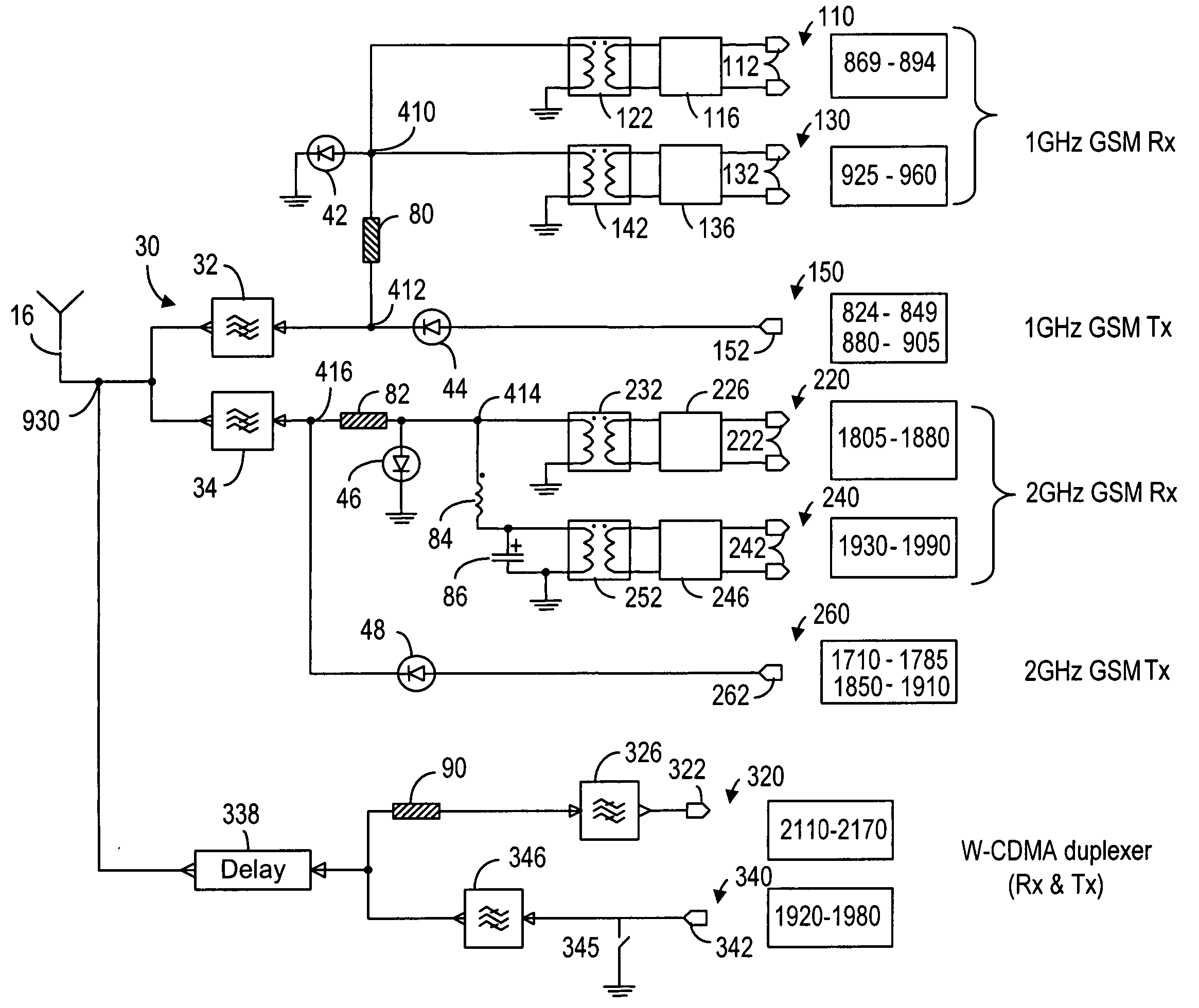
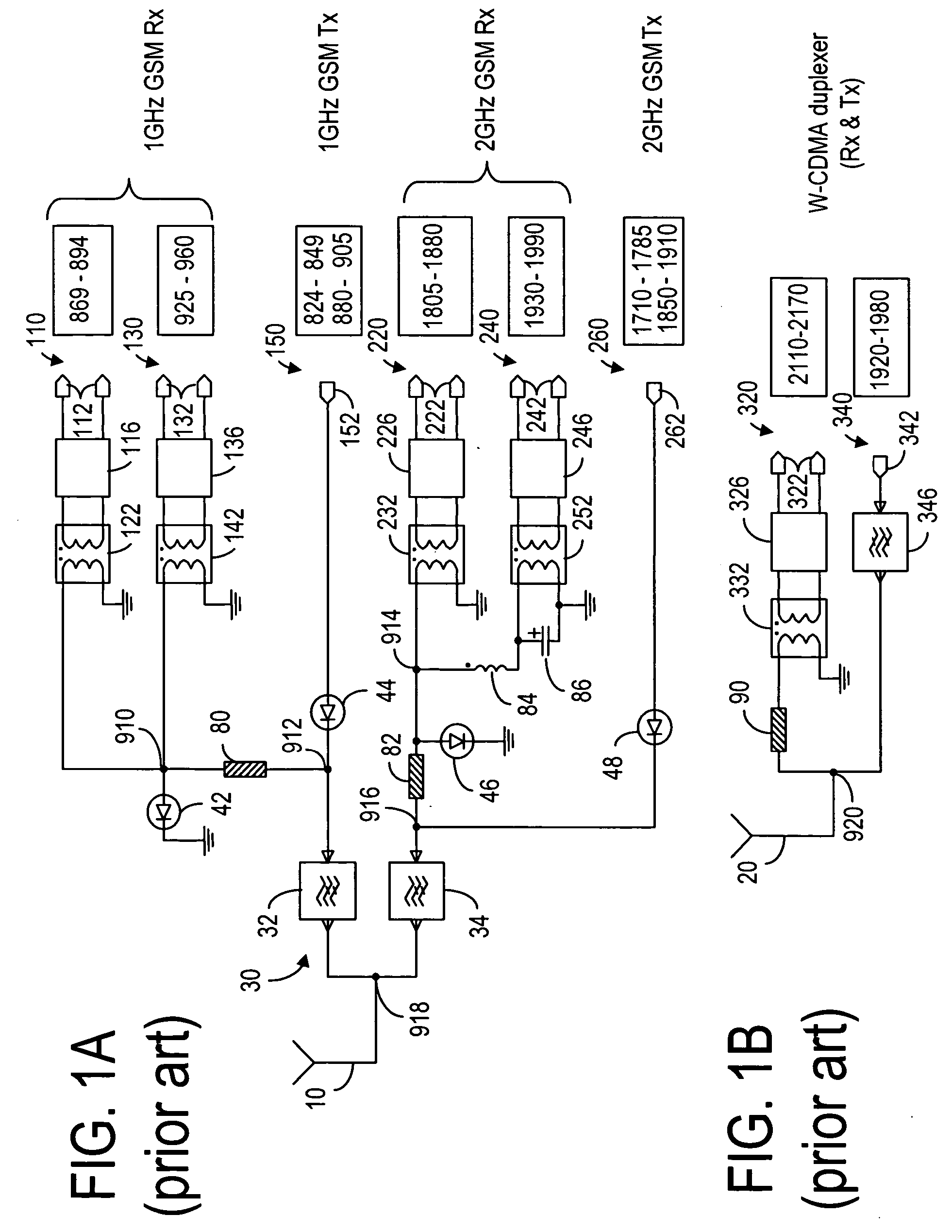
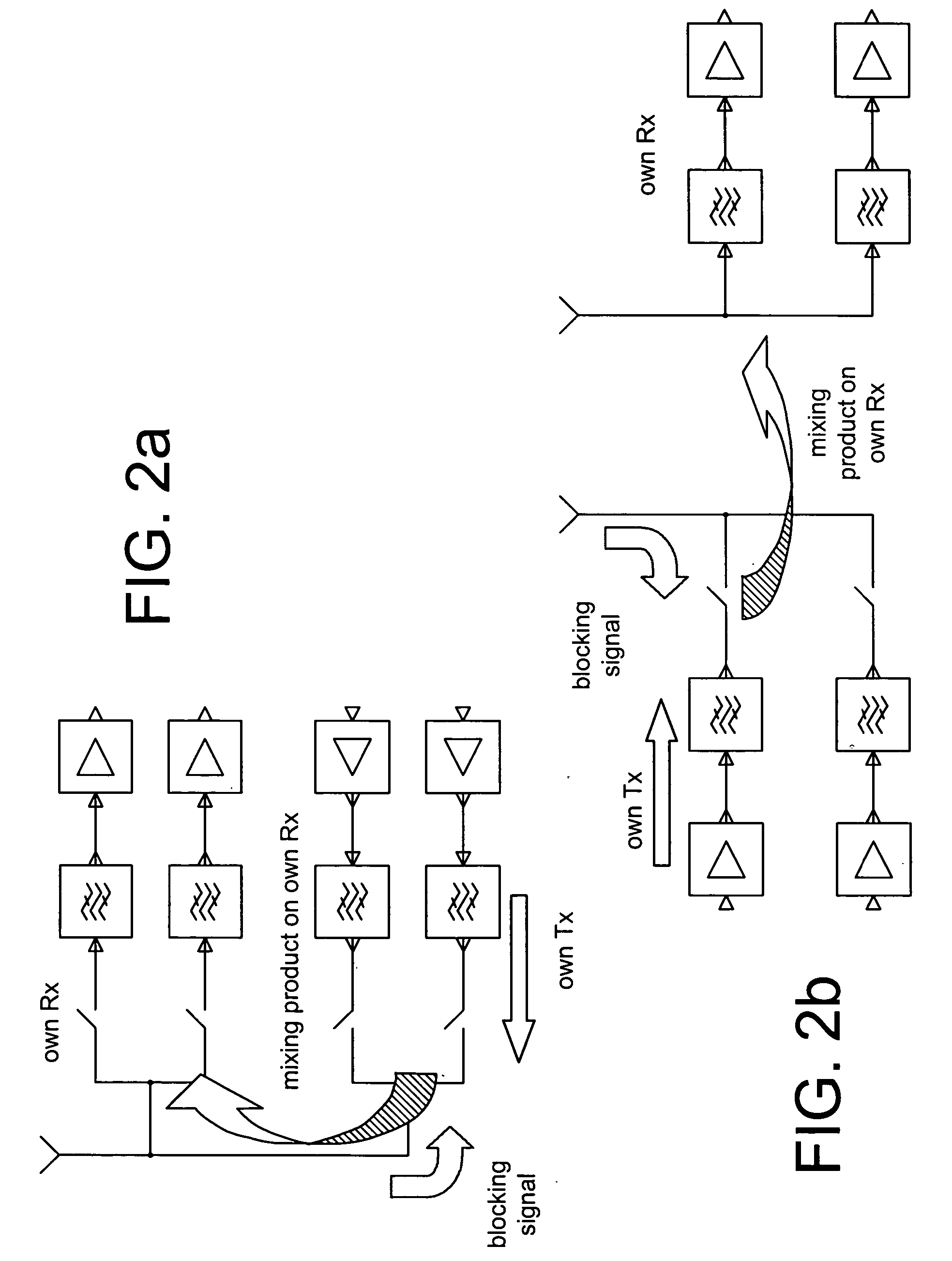
[0114] The present invention makes use of separate Rx / Tx paths and switches in the RX paths to provide sufficient cross-band isolation between bands. An example of cross-band isolation is shown in FIG. 3a. As shown in FIG. 3a, the upper band Tx chain connected to the antenna 10 includes 1800GSM Tx—3 (1710-1785 MHz): 1900GSM Tx—4 (1850-1910 MHz) and W-CDMA (EU) Tx—7 (1920-1980 MHz), and the upper band Rx chain connected to the antenna 20 includes 1800GSM Rx—3 (1805-1880 MHz), 1900GSM Rx—4 (1930-1990 MHz) and W-CDMA (EU) Rx—7 (2110-2170 MHz). Thus, the frequency overlap in these chains is: Tx—4-Rx—3 (30 MHz, from 1850 to 1880 MHz), and Tx—7-Rx—4 (50 MHz, from 1930 to 1980 MHz). The cross band problems are also illustrated in FIG. 3b. If the maximum output power at the antenna in Tx mode is 30 to 33 dBm (depending on system standard) and a typical isolation that can be achieved between two separate antennas is between 10 to 20 dBm, for example, then the power level at the Rx antenna is...


PUM


Abstract

The combination of filters and switches is used to solve the non-linearity problems in GSM/W-CDMA transceiver front-end wherein one common antenna is used for both the GSM mode and the W-CDMA mode. In particular, separate Rx/Tx paths and switches in the Rx paths are used to provide cross-band isolation between bands. All of the switches in the transceiver are disposed after the filters in that no switches are disposed between the filters and the antenna. Furthermore, bandpass filters are matched to one common node even if they are only disconnected at the output as long as the impedance at the output can be controlled.

Description

CROSS REFERENCES TO RELATED APPLICATIONS [0001] The present application is related to U.S. patent applications with Ser. Nos. 10 / 688,181, 10 / 688,275 and 10 / 688,807, all filed on Oct. 17, 2003, and assigned to the assignee of the present application. The present invention is also related to U.S. patent application Ser. No. ______, Docket No. 944-003.230, assigned to the assignee of the present invention, and filed even date herewith.FIELD OF THE INVENTION [0002] The present invention relates generally to front-end topology and, more particularly, to front-end arrangement for multiband and / or multimode mobile cellular handset electronics. BACKGROUND OF THE INVENTION [0003] The term “front-end”, as used in this disclosure, means the components and functions between the antennas and the power amplifiers or RF-ASIC (radio frequency application specific integrated circuit), but some front-end modules may also include power amplifiers. The front-end in multiband, multimode engines, especia...

Claims


Application Information

Patent Timeline
IPC IPC(8): H03H7/46H04B1/06H04B1/40H04B1/44
CPCH04B1/005H04B1/406H04B1/0057H04B1/48H04B1/44
Inventor ELLA, JUHARANTA, TERO
Owner NOKIA CORP
Why Eureka
Try Eureka