Implantable urinary tract monitor

a urinary tract monitor and implantable technology, applied in the field of medical sensors, can solve the problems of altering the physiological function of the urinary tract of the patient, persistent catheterization, patient discomfort, etc., and achieve the effects of reducing the impact on normal physiological function, reducing the delay between analysis, and reducing significant discomfor

Inactive Publication Date: 2005-11-03
MEDTRONIC INC
View PDF15 Cites 114 Cited by
  • Summary
  • Abstract
  • Description
  • Claims
  • Application Information

AI Technical Summary

Benefits of technology

[0016] In comparison to known techniques for urodynamic testing or urinalysis, various embodiments of the invention may provide one or more advantages. For example, an implantable urinary tract monitor permits urodynamic testing or urinalysis to be performed on a substantially continuous basis, if desired, without the need for persistent catheterization in the case of urodynamic testing, or repeated catheterizations or repeated voided urine collection to obtain urine samples in the case of urinalysis. In addition, following initial placement with a catheter, cystoscope, or the like, there is no need for persistent catheterization, eliminating significant discomfort and reducing the impact on normal physiological function of the patient's urinary tract. Also, the monitor may reduce delays between analysis and generation of results, and accompany a patient throughout a routine of daily activities.

Problems solved by technology

These problems include the need for persistent catheterization to perform urodynamic testing, or catheterization to obtain a urine sample, or the capture of a voided urine sample.
Additional problems relate to the need for repeated catheterization or repeated capture of samples for further urodynamic testing or urinalysis.
As further problems, existing techniques for urodynamic testing or urinalysis may cause patient discomfort, and alter the physiological function of the patient's urinary tract.
In addition, urodynamic testing and especially urinalysis may suffer from delays between catheterization or sample-taking and generation of results.
In addition, other problems relate to the inability to track urodynamic conditions or perform urinalysis continuously or over an extended period of time, especially as the patient goes about his or her daily routine.
Instead, existing techniques are often restricted to hospital stays, clinical visits, or individual samples, and therefore produce results for limited sets of data points.

Method used


Image

  • Implantable urinary tract monitor
  • Implantable urinary tract monitor
  • Implantable urinary tract monitor

Examples


Embodiment Construction

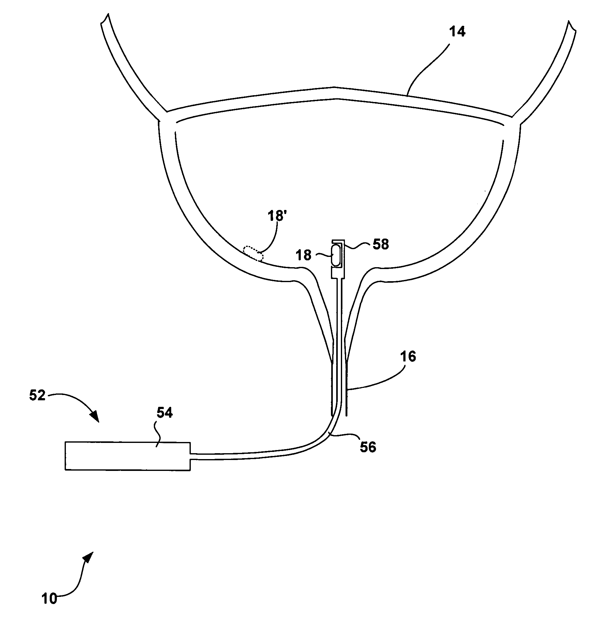
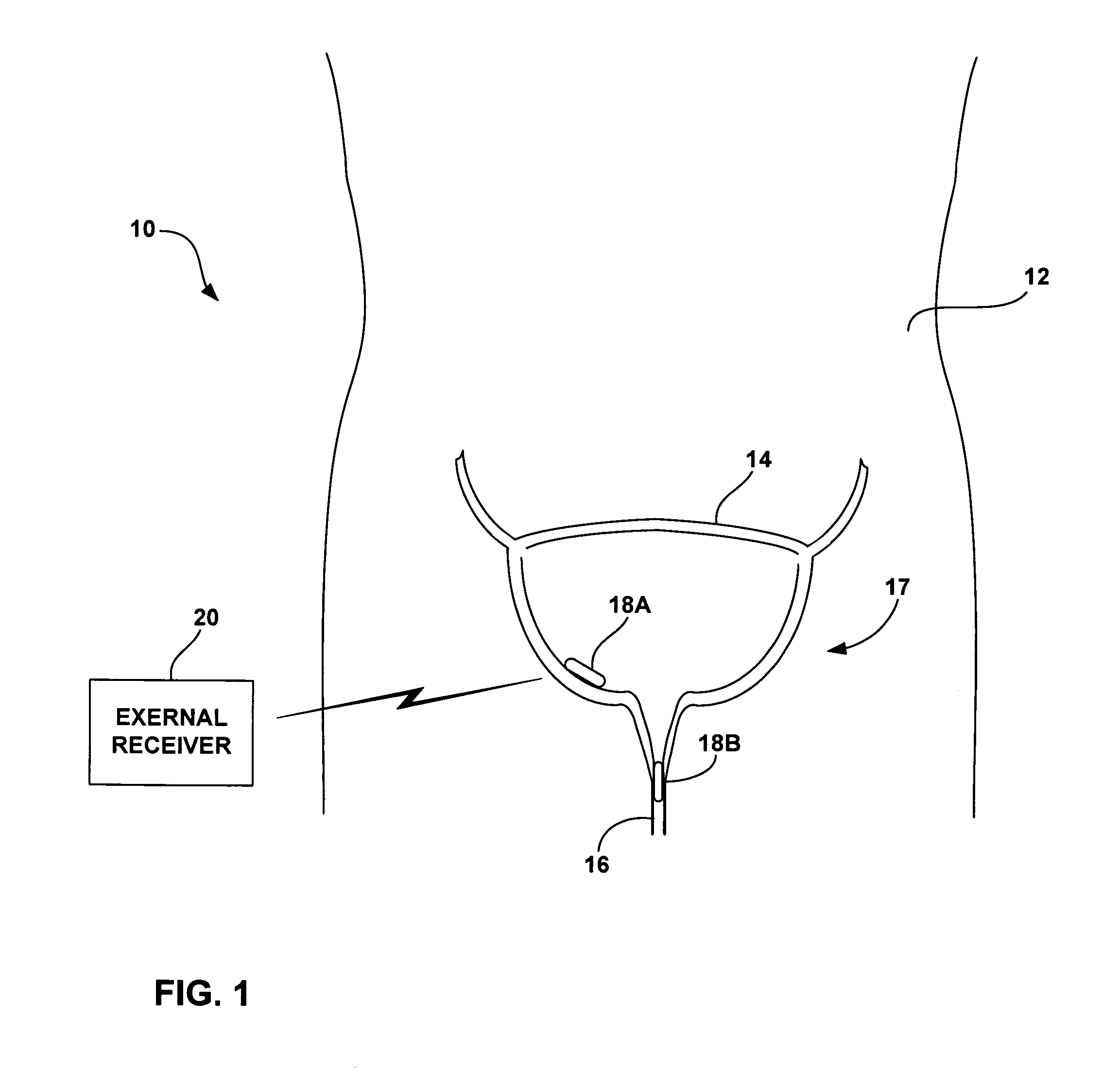
[0037]FIG. 1 is a schematic diagram illustrating an implantable urinary tract monitor system 10 shown in conjunction with a patient 12 and, in particular, a patient bladder 14 and urethra 16 forming part of the patient's urinary tract 17. As shown in FIG. 1, system 10 includes an implanted monitor 18A or 18B and an external receiver 20. Monitor 18A is shown at a target location within bladder 14, and monitor 18B is shown at a target location within urethra 16. One or more urinary tract monitors 18A, 18B may be placed within urinary tract 17. However, two monitors 18A, 18B are shown in FIG. 1 primarily to depict different placement positions for a single monitor, rather than the use of multiple monitors, although multiple monitors are possible. Monitors 18A, 18B will be generally referred to herein collectively as monitor 18.

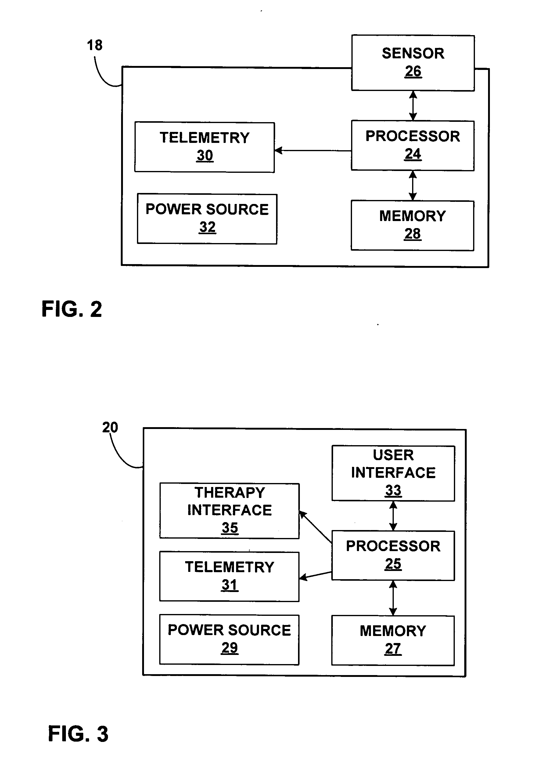
[0038] An implantable urinary tract monitor 18 may be configured to sense one or more physiological conditions within urinary tract 17. For example, the physiol...


PUM

PropertyMeasurementUnit
widthaaaaaaaaaa
widthaaaaaaaaaa
diameteraaaaaaaaaa

Abstract

An implantable urinary tract monitor is configured for indwelling urodynamic testing, indwelling urinalysis, or both. A urinary tract monitor in accordance with the invention incorporates a fixation structure to selectively position the monitor at a tissue site within the bladder or urethra. In this manner, the monitor is implanted within the patient and, if desired, can accompany the patient throughout a routine of normal daily activities.

Description

FIELD OF THE INVENTION [0001] The invention relates to medical sensors and, more particularly, sensors for sensing physiological conditions within a urinary tract. BACKGROUND [0002] One form of urinary tract analysis is urodynamic testing. Many people suffer from involuntary urine leakage, i.e., urinary incontinence. Others may suffer from blocked or restricted urine flow. Other urinary disorders include frequent urination, sudden urges to urinate, problems starting a urine stream, painful urination, problems emptying the bladder completely, and recurrent urinary tract infections. A physician uses a urodynamic test to study how a patient stores and releases urine. [0003] Different muscles, nerves, organs and conduits within the urinary tract cooperate to collect, store and release urine. A variety of disorders may compromise the urinary tract performance and contribute to incontinence or restricted flow. Many of the disorders may be associated with aging, injury or illness. For exam...

Claims


Application Information

Patent Timeline
Patent Type & Authority Applications(United States)
IPC IPC(8): A61B5/00A61B5/03A61K31/54
CPCA61B5/0002A61B5/0028A61B5/01A61B5/14532A61B5/14539A61B5/202A61K31/54A61B5/205A61B5/208A61B5/68A61B5/6874A61B5/6882A61B2560/0219A61B5/204
Inventor CHRISTOPHERSON, MARK A.STARKEBAUM, WARREN L.
Owner MEDTRONIC INC
Why Eureka
Try Eureka