Systems and methods for precharging circuitry for pulse generation

a pre-charging circuit and pulse generation technology, applied in the field of pulse generation, can solve the problems of poor slew rate, low power amplifier, high power consumption of high frequency operation, etc., and achieve the effects of low power consumption, low cost, and low power consumption

Active Publication Date: 2005-11-03
ADVANCED NEUROMODULATION SYST INC
View PDF9 Cites 84 Cited by
  • Summary
  • Abstract
  • Description
  • Claims
  • Application Information

AI Technical Summary

Benefits of technology

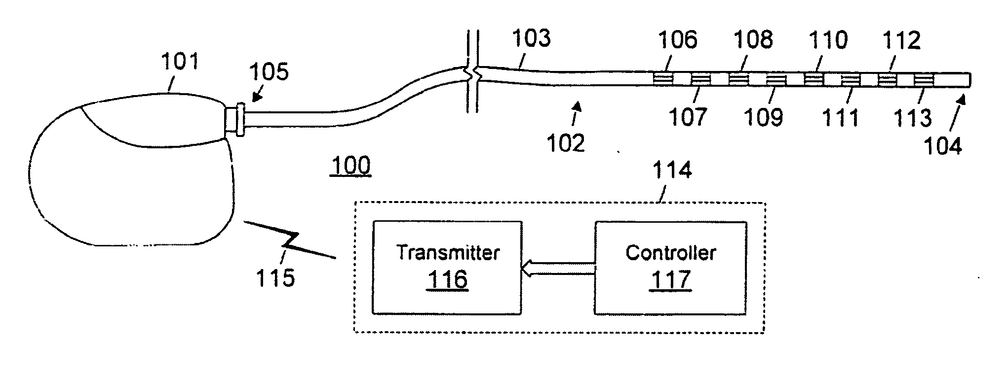
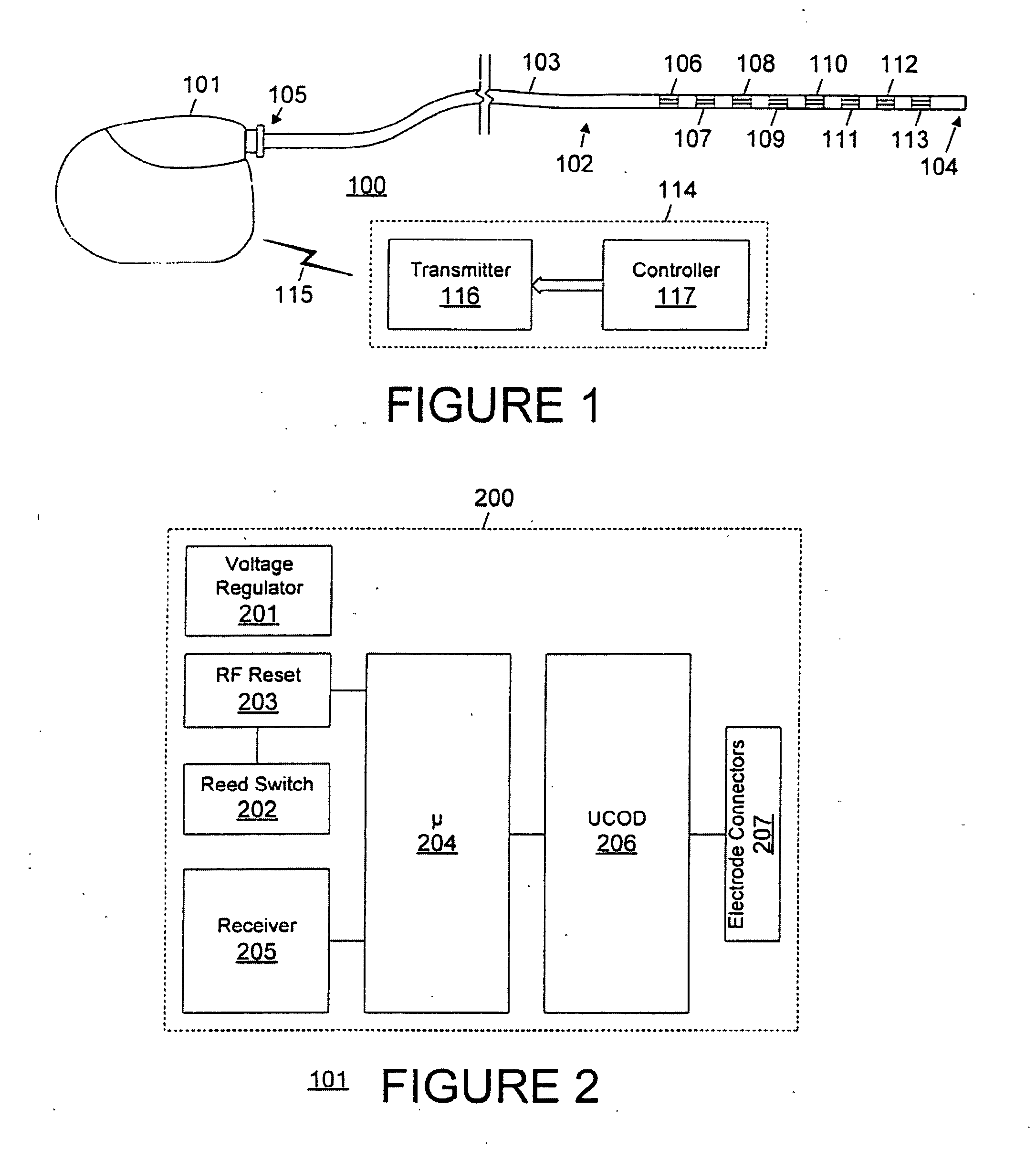
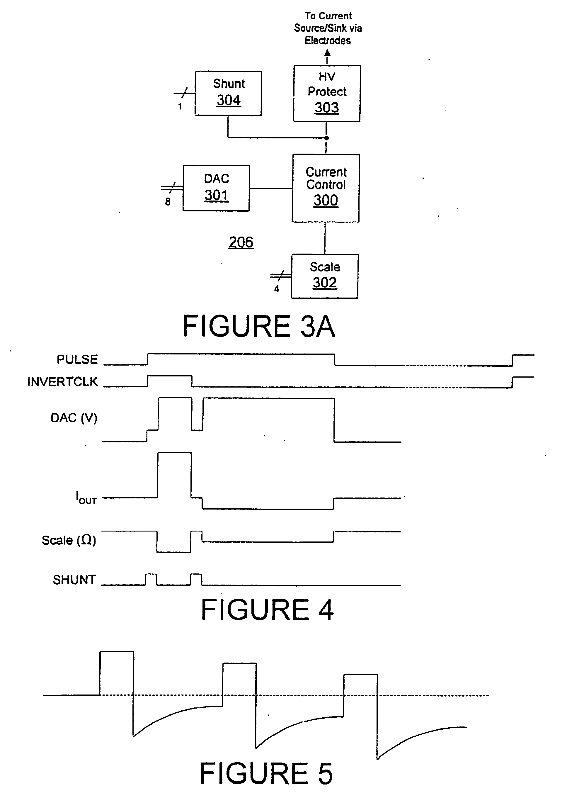
[0004] Embodiments of the present invention provide generation of pulses at high frequencies with low power consumption using techniques for precharging circuitry used in pulse generation. For example, an electrical stimulation pulse delivered to a patient through anode and cathode electrodes is delivered using an amplifier for providing a programmable constant current stimulation pulse. Embodiments of the present invention enables use of a low power (and lower cost) implementation of the foregoing amplifier by providing a pre-charge period for each pulse.

Problems solved by technology

For example, operational amplifiers having a slew rate acceptable for high frequency operation typically have high power consumption, an important consideration for battery life and / or the interval between required recharging cycles.
Low power amplifiers, on the other hand, have a poor slew rate that can constrain the frequency or duration of electrical stimulation pulses, or simply provide poor stimulation performance.

Method used


Image

  • Systems and methods for precharging circuitry for pulse generation
  • Systems and methods for precharging circuitry for pulse generation
  • Systems and methods for precharging circuitry for pulse generation

Examples


Embodiment Construction

[0015]FIGS. 1 through 7, discussed below, and the various embodiments used to describe the principles of the present invention in this patent document are by way of illustration only and should not be construed in any way to limit the scope of the invention. Those skilled in the art will understand that the principles of the present invention may be implemented in any suitably arranged device.

[0016] Before undertaking the detailed description below, it may be advantageous to set forth definitions of certain words or phrases used throughout this patent document: the terms “include” and “comprise,” as well as derivatives thereof, mean inclusion without limitation; the term “or” is inclusive, meaning and / or; the phrases “associated with” and “associated therewith,” as well as derivatives thereof, may mean to include, be included within, interconnect with, contain, be contained within, connect to or with, couple to or with, be communicable with, cooperate with, interleave, juxtapose, b...


PUM


Abstract

A low power (and lower cost) implementation for amplifier used in delivering a stimulation pulse is provided according to embodiments through use of a pre-charge period for each pulse. For example, a voltage at a variable output terminal of a digital-to-analog converter is increased on the leading edge of PULSE and INVERTCLK signals to result in an output of an operational amplifier increasing to a predetermined voltage prior to output of a stimulation pulse, according to an embodiment. A shunt path may be implemented to shunt current away from a load during the pre-charge period.

Description

CROSS-REFERENCE TO RELATED APPLICATIONS [0001] The present application claims priority to co-pending U.S. Provisional Patent Application Ser. No. 60 / 561,437, entitled “PULSE GENERATION CIRCUIT UNIVERSAL CUSTOM OUTPUT DRIVER,” filed Apr. 12, 2004, the disclosure of which is hereby incorporated herein by reference. The present application is related to concurrently filed and commonly assigned U.S. patent application Ser. No. [Attorney Docket No. 03-035] entitled “SYSTEMS AND METHODS FOR PROVIDING AMPLITUDE SELECTION FOR PULSE GENERATION,” U.S. patent application Ser. No. [Attorney Docket No. 03-037] entitled “ACTIVE DISCHARGE SYSTEMS AND METHODS,” U.S. patent application Ser. No. [Attorney Docket No. 03-038] entitled “FRACTIONAL VOLTAGE CONVERTER,” and U.S. patent application Ser. No. [Attorney Docket No. 03-040] entitled “VOLTAGE LIMITED SYSTEMS AND METHODS,” the disclosures of which are hereby incorporated herein by reference.TECHNICAL FIELD [0002] The present invention is directed,...

Claims


Application Information

Patent Timeline
Patent Type & Authority Applications(United States)
IPC IPC(8): A61N1/08A61N1/36A61N1/37A61N1/378H02M3/07H03K5/02
CPCA61N1/3782H02M3/07A61N1/36153H02M2003/072A61N1/36125H02M3/073H02M3/072
Inventor VARRICHIO, ANTHONY J.TRANCHINA, BENJAMIN A.
Owner ADVANCED NEUROMODULATION SYST INC
Why Eureka
Try Eureka