Artificial intervertebral disc having a universal joint

a technology of intervertebral discs and universal joints, which is applied in the field of artificial intervertebral discs having universal joints, can solve the problems of limiting the ability of straps to come into contact with the bottom surface of grooves, and achieve the effect of increasing the range of motion

Inactive Publication Date: 2005-11-03
HOWMEDICA OSTEONICS CORP
View PDF99 Cites 49 Cited by
  • Summary
  • Abstract
  • Description
  • Claims
  • Application Information

AI Technical Summary

Benefits of technology

[0024] The artificial intervertebral disc of the present invention also includes a second baseplate having a top surface, a bottom surface and a cavity exposed at the top surface of the second baseplate. The cavity preferably includes a groove having a first sidewall and a second sidewall, with the sidewalls being remote from each other. A spherical element having a central point is disposed within the aperture of the first baseplate and overlies the strap. The spherical element is preferably attached to the first sidewall and second sidewall of the second baseplate such that the strap is positioned and captured within the groove, thereby permitting the first baseplate and the second baseplate to move in an angulational direction and a rotational direction relative to one another with the strap translating about the central point of the spherical element.
[0025] The first sidewall and second sidewall may each include an indent such that the spherical element is attached to the first sidewall and second sidewall at respective indents. Additionally, the first sidewall and second sidewall may have a plurality of ends that are angled, such that during rotational movement of the first baseplate or second baseplate the strap has an increased range of motion within the groove.

Problems solved by technology

Additionally, the groove has a depth, which, in conjunction with the space between the first baseplate and the ball, limits the ability of the strap to come into contact with a bottom surface of the groove, even during axial movement of the two baseplates.

Method used


Image

  • Artificial intervertebral disc having a universal joint
  • Artificial intervertebral disc having a universal joint
  • Artificial intervertebral disc having a universal joint

Examples


Embodiment Construction

[0042] The present invention will now be described with reference to the accompanying figures. The embodiments described herein are meant to be illustrative of the present invention and in no way should be thought of as limiting the present invention.

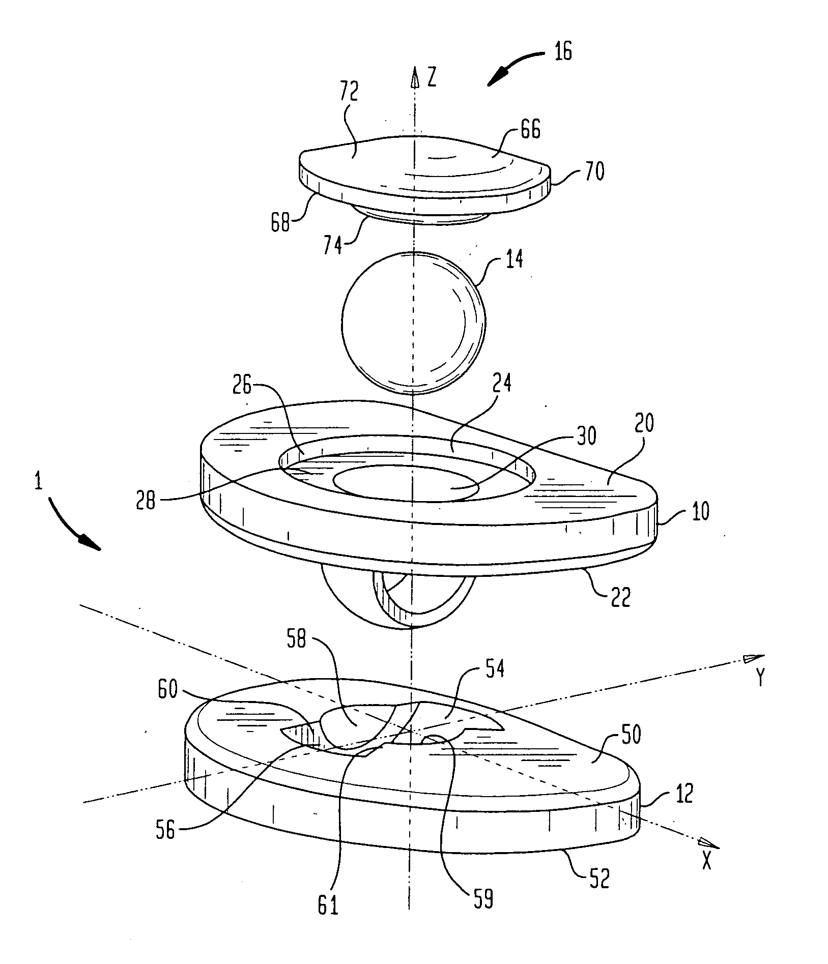
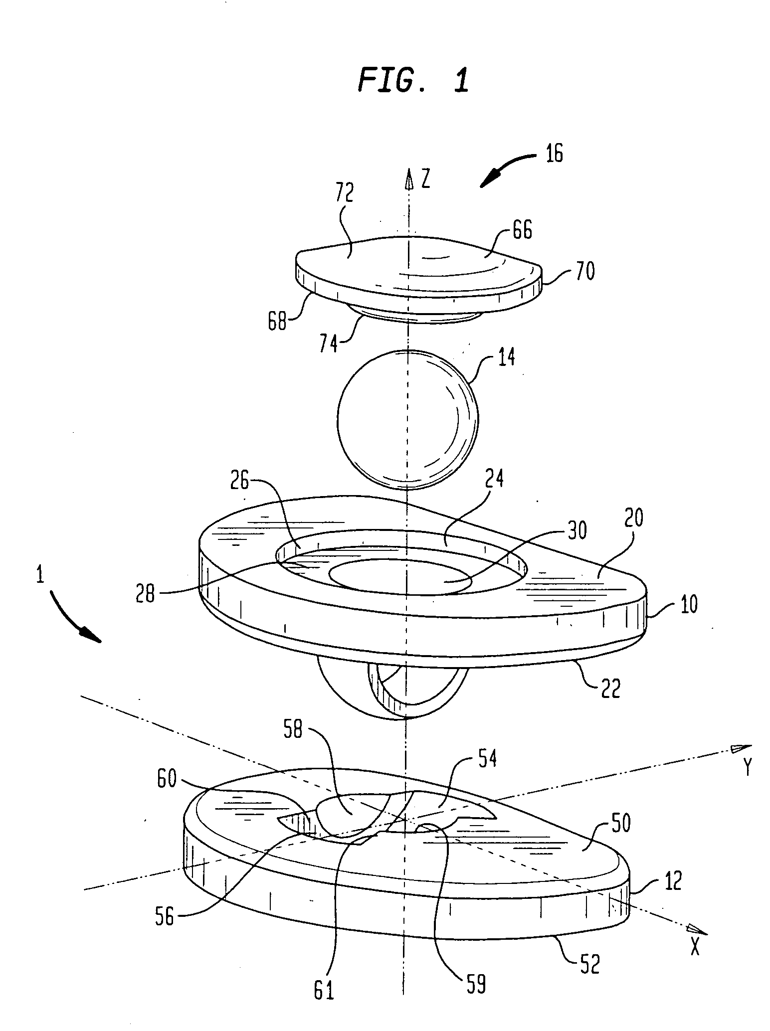
[0043] As shown in FIG. 1, an artificial intervertebral disc 1, according to the present invention, preferably includes an upper baseplate 10, a lower baseplate 12, a ball 14 and a cover 16. Upper baseplate 10 is provided with a top surface 20 and a bottom surface 22. Disposed within the boundary of top surface 20 is a recess 24. Recess 24 includes a circular skirt 26 positioned adjacent top surface 20 and defining the outer boundary of recess 24. Recess 24 further includes a shoulder 28 defining a lower limit of the recess. An aperture 30 is disposed adjacent shoulder 28 and extends from the shoulder to bottom surface 22 of upper baseplate 10.

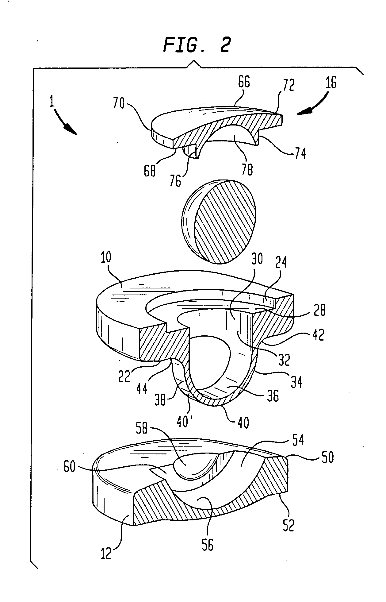
[0044] As best shown in FIG. 2 aperture 30 is defined by circumferential wall 32 which exten...


PUM


Abstract

An artificial intervertebral implant including a first baseplate having a top surface, a bottom surface, an aperture extending therethrough and a strap attached to the bottom surface of the first baseplate and underlying the aperture. The implant further includes a second baseplate juxtaposed with the first baseplate. The second baseplate includes a top surface with a cavity exposed therein. An articulating element is attached to a pair of opposing sidewalls of the cavity for retaining the strap within the cavity.

Description

CROSS-REFERENCE TO RELATED APPLICATIONS [0001] This application claims the benefit of the filing date of U.S. Provisional Patent Application No. 60 / 546,230 filed Feb. 20, 2004, the disclosure of which is hereby incorporated by reference herein.BACKGROUND OF THE INVENTION [0002] The bones and connective tissue of an adult human spinal column consist of more than twenty discrete bones coupled sequentially to one another by a tri-joint complex, which consists of an anterior disc and two posterior facet joints, the anterior discs of adjacent bones being cushioned by cartilage spacers referred to as intervertebral discs. These more than twenty bones are anatomically categorized as being members of one of four classifications: cervical, thoracic, lumbar, or sacral. The cervical portion of the spine, which comprises the top of the spine up to the base of the skull, includes the first seven vertebrae. The intermediate twelve bones are the thoracic vertebrae, and connect to the lower spine c...

Claims


Application Information

Patent Timeline
Patent Type & Authority Applications(United States)
IPC IPC(8): A61B17/58A61F2/00A61F2/30A61F2/44
CPCA61F2/30744A61F2/4425A61F2002/30242A61F2002/30362A61F2002/30448A61F2230/0071A61F2002/30685A61F2002/443A61F2220/0033A61F2220/005A61F2002/30663
Inventor ZUBOK, RAFAILDUDASIK, MICHAEL W.ERRICO, JOSEPH P.
Owner HOWMEDICA OSTEONICS CORP
Why Eureka
Try Eureka