High speed multiplication apparatus of Wallace tree type with high area efficiency
a multiplication apparatus and high area efficiency technology, applied in the field of multiplication apparatuses, can solve the problems of limited speed, reduced number of addition circuit stages, and inability to perform multi-bit multiplication, and achieve the effect of high speed multiplication
- Summary
- Abstract
- Description
- Claims
- Application Information
AI Technical Summary
Benefits of technology
Problems solved by technology
Method used
Image
Examples
first embodiment
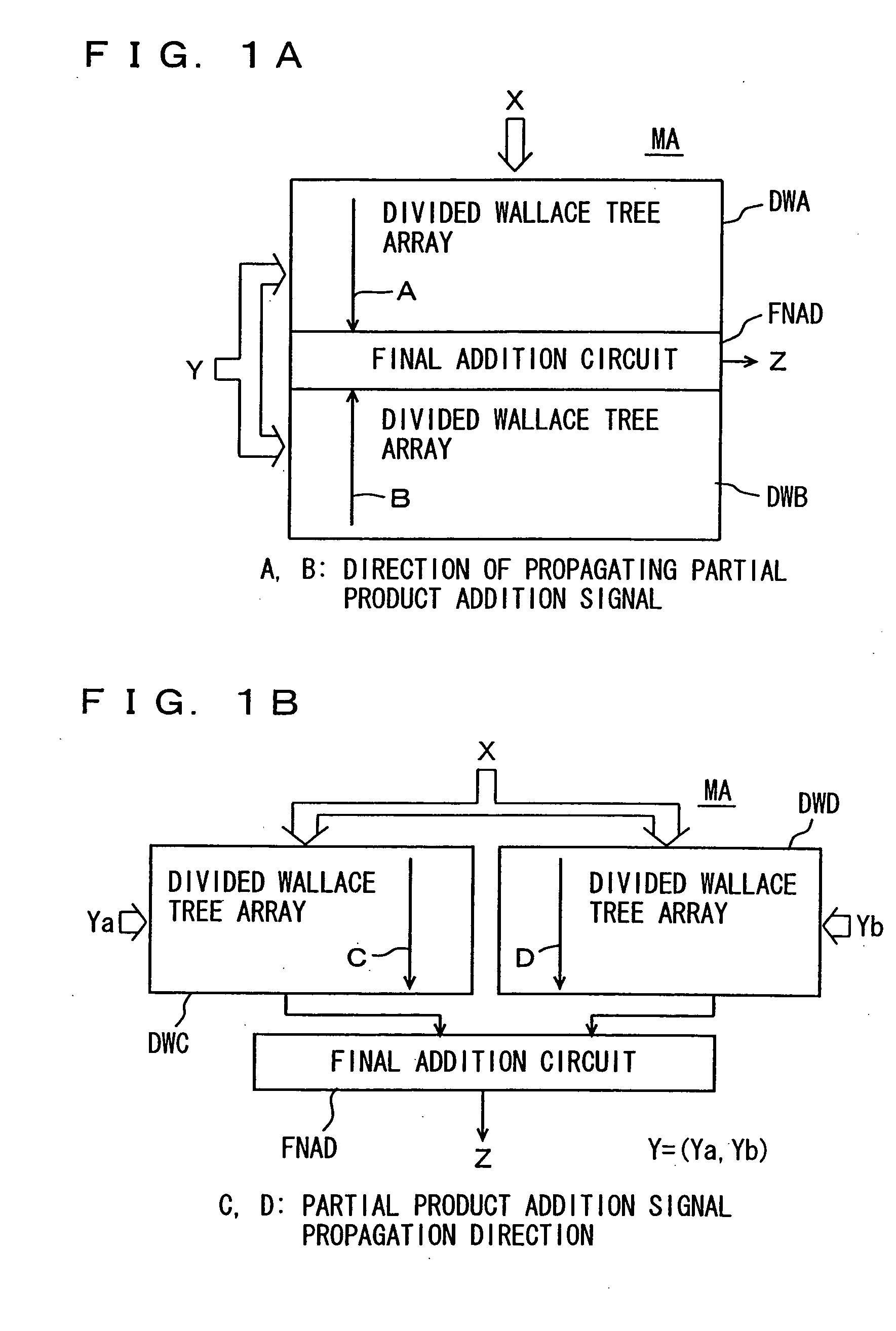
[0057]FIG. 1A is a diagram schematically showing an arrangement of a multiplication array of a multiplication apparatus according to the first embodiment of the present invention. Referring to FIG. 1A, a multiplication array MA includes two divided Wallace tree arrays DWA and DWB divided at a specific bit position of multiplier Y. A final addition circuit FNAD is arranged between divided Wallace tree arrays DWA and DWB. Divided Wallace tree arrays DWA and DWB transmit addition results toward final addition circuit FNAD. Thus, the addition circuit stages of the Wallace tree in multiplication array MA are divided by divided Wallace tree arrays DWA and DWB, so that a critical path for transmitting the addition results of partial products is reduced in length for high speed multiplication.
[0058] It is noted that the most significant bit of multiplicand X may be on the right or left side of FIG. 1A of divided Wallace tree arrays DWA and DWB. For a multiplier Y, on the other hand, the bi...
second embodiment
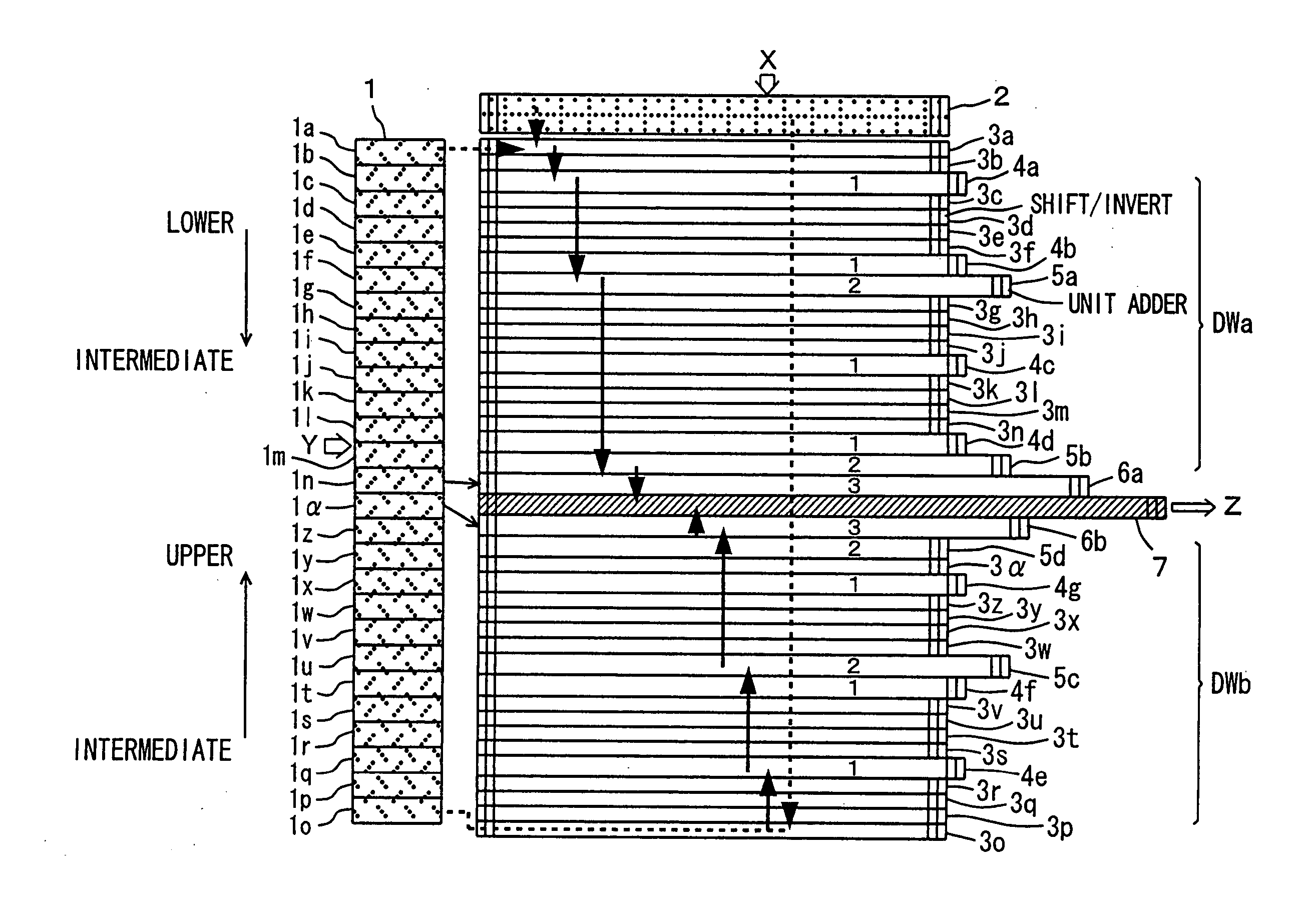
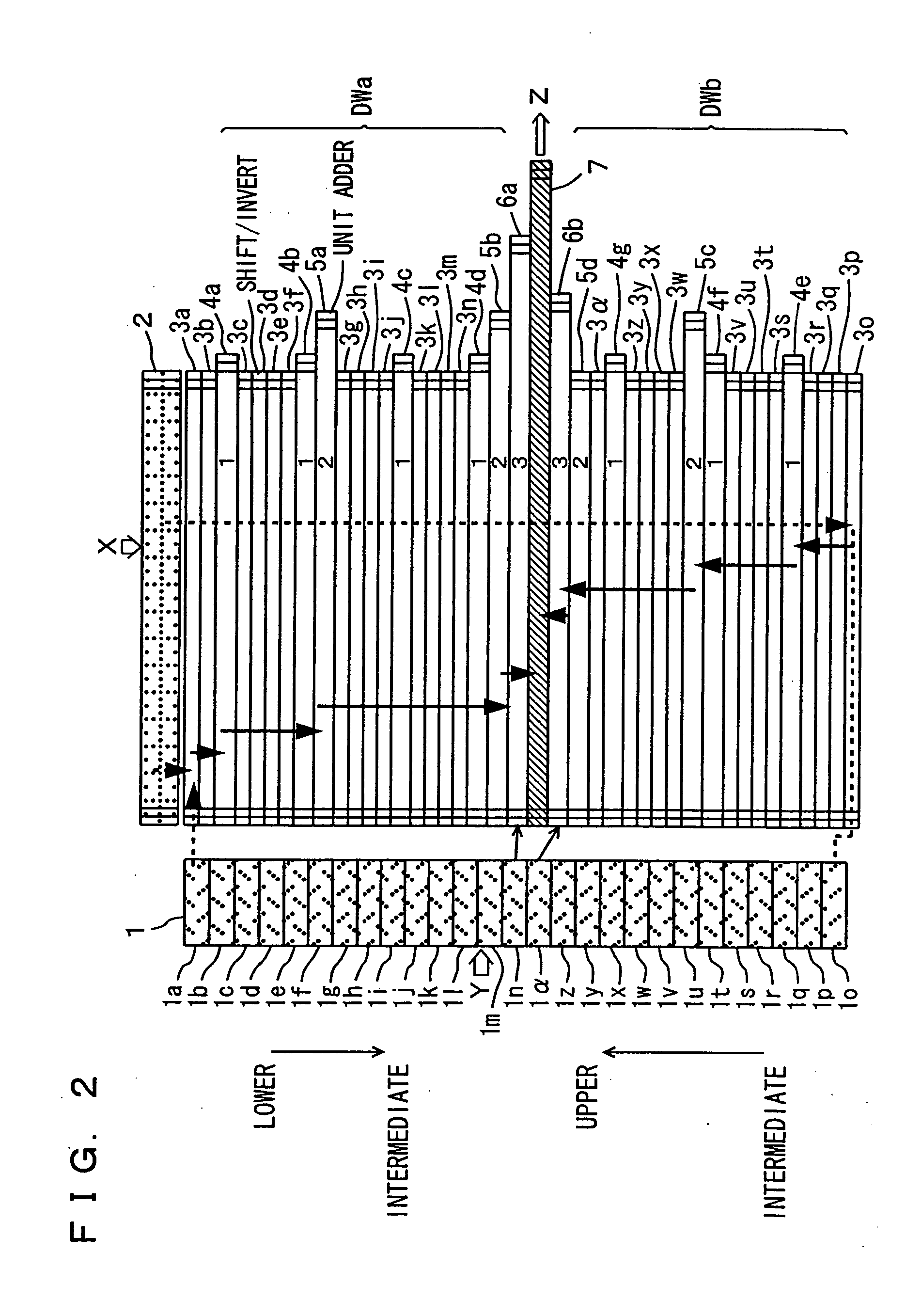
[0064]FIG. 2 is a diagram schematically showing a configuration of a multiplication apparatus according to the second embodiment of the present invention. The multiplication apparatus according to the present invention, which will be described with reference to FIG. 2 and the following figures, performs multiplication of 54-bit multiplier Y and 54-bit multiplicand X in accordance with the second order Booth algorithm.
[0065] Referring to FIG. 2, a multiplication array is divided into divided arrays DWa and DWb. Divided array DWa includes: Booth selectors 3a to 3n generating the 0-th order partial products from multiplicand data from a multiplicand register circuit 2 in accordance with select control signals from Booth encode circuits 1a to in included in a Booth encoder 1; the first order 4:2 addition circuits 4a to 4d adding the 0-th order partial products generated by Booth selectors 3a to 3n for generating the first order partial products; the second order 4:2 addition circuits 5...
third embodiment
[0078]FIG. 5 is a diagram schematically showing a configuration of an array portion of a multiplication apparatus according to the third embodiment of the present invention. Referring to FIG. 5, in the multiplication apparatus, the multiplication array is divided into two divided arrays DWa and DWb. A final addition circuit 7 is arranged between divided arrays DWa and DWb. This configuration is the same as in the second embodiment described with reference to FIG. 2. In the third embodiment, a multiplicand register circuit 2 is arranged adjacent to final addition circuit 7 between divided arrays DWa and DWb, receives a multiplicand X and applies multiplicand data to Booth selectors 3a to 3a. Thus, multiplicand register circuit 2 transmits the multiplicand data in the opposite directions for divided arrays DWa and DWb.
[0079] Corresponding to divided arrays DWa and DWb, Booth encoder 1 is also divided into two divided encoders 1A and 1B.
[0080] In the configuration shown in FIG. 5, as...
PUM
 Abstract
Description
Claims
Application Information
 - R&D
- Intellectual Property
- Life Sciences
- Materials
- Tech Scout
- Unparalleled Data Quality
- Higher Quality Content
- 60% Fewer Hallucinations
Browse by: Latest US Patents, China's latest patents, Technical Efficacy Thesaurus, Application Domain, Technology Topic, Popular Technical Reports.
© 2025 PatSnap. All rights reserved.Legal|Privacy policy|Modern Slavery Act Transparency Statement|Sitemap|About US| Contact US: help@patsnap.com


