Floating point number storage method and floating point arithmetic device

a technology of floating point and arithmetic device, which is applied in the direction of instruments, computation using denominational number representation, computation using non-denominational number representation, etc., can solve the problems of enormous processing volume, enormous processing volume, and enormous processing volume, and achieve the effect of extremely high practical value of the present invention

Active Publication Date: 2003-12-25
PANASONIC CORP
View PDF3 Cites 10 Cited by
  • Summary
  • Abstract
  • Description
  • Claims
  • Application Information

AI Technical Summary

Benefits of technology

0044] As described above, the present invention allows multiplication of floating point numbers using an arithmetic unit for fixed point numbers without any special circuit or the like if only the conventional floating point format is modified. In addition, the present invention realizes high-speed multiplication and representation of floating point numbers in integers, and thus the practical value of the present invention is extremely high particularly as a technique for high-speed processing of multimedia data such as audio and video processing requiring a heavy use of multiplication processing.

Problems solved by technology

However, in the above-mentioned floating point number storage format, in order to extract only the value of the exponent, the most significant 1 bit and the lower 23 bits need to be separated from the 32-bit data, which requires an enormous amount of processing.
On the other hand, in order to extract only the value of the mantissa, the above-mentioned processing of (1.multidot.k) needs to be performed after only the value of the lower 23 bits is extracted, which also requires an enormous amount of processing.
This processing requires an enormous amount of processing.
On the other hand, in the above-mentioned fixed point number storage format, although the processing amount is less than that in the floating point format because there is no need to separate the exponents and the mantissas for arithmetic, there is a problem that the range of representable numbers are limited.

Method used


Image

  • Floating point number storage method and floating point arithmetic device
  • Floating point number storage method and floating point arithmetic device
  • Floating point number storage method and floating point arithmetic device

Examples


first embodiment

[0061] (First Embodiment)

[0062] The floating point number storage method in the first embodiment of the present invention will be explained below with reference to drawings.

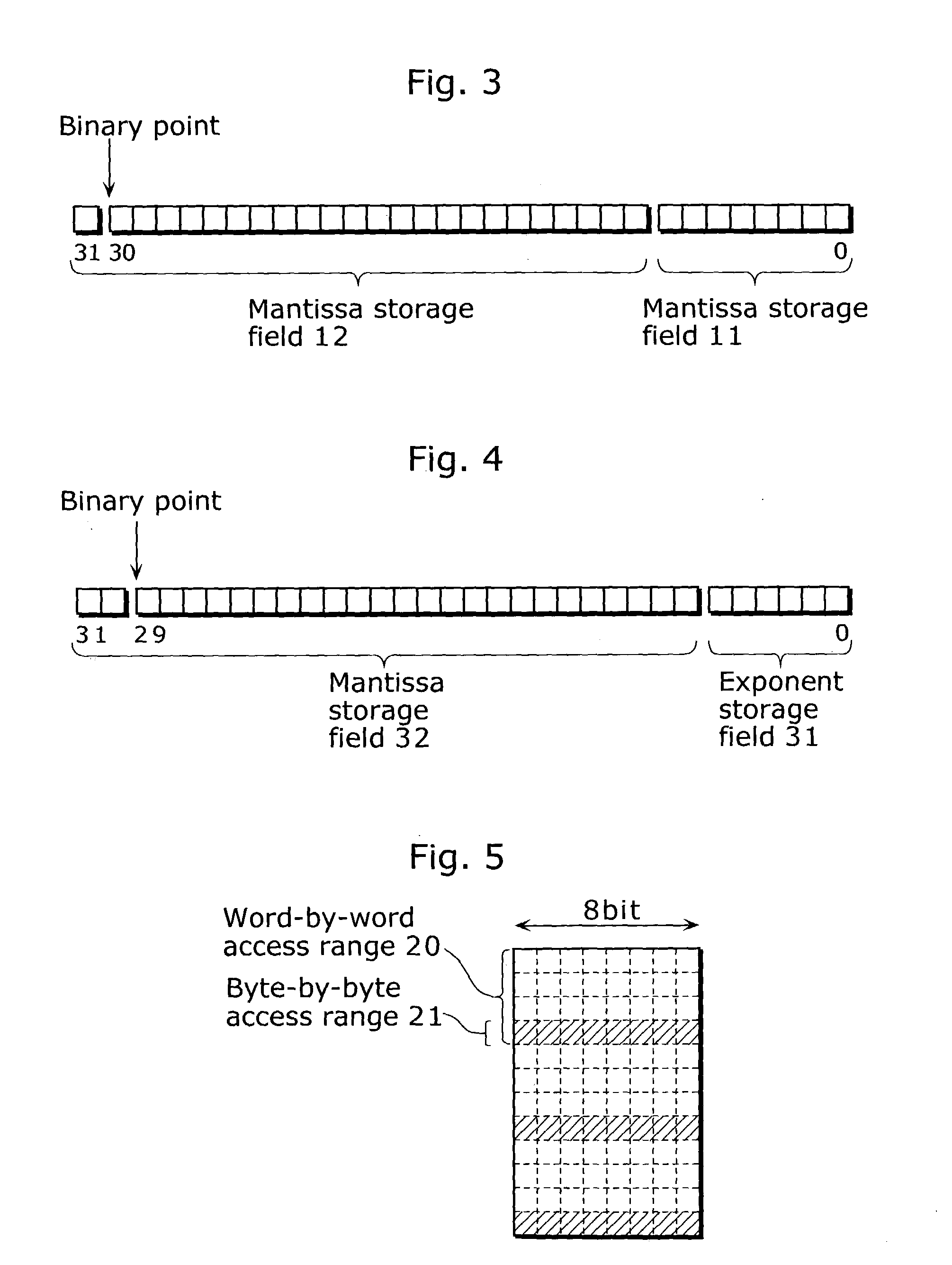
[0063] FIG. 3 is a diagram showing a bit field of a real number x to be stored by the floating point number storage method in the first embodiment of the present invention. This bit field includes an exponent storage field 11 and a mantissa storage field 12.

[0064] In the exponent storage field 11, the value n is stored as an 8-bit integer where the real number x is represented by a*2{circumflex over ( )}n. The value is represented in two's complement, for instance. In the mantissa storage field 12, the value x is stored in 24 bits where the real number x is represented by a*2{circumflex over ( )}n. The value is represented by a fixed point number whose binary point is fixedly placed. In the present embodiment, the value a is normalized so as to be within the range of -1.about.+1. Therefore, this 24-bit structure,...

second embodiment

[0094] (Second Embodiment)

[0095] Next, the floating point arithmetic device according to the second embodiment of the present invention will be explained with reference to the figures.

[0096] FIG. 6 is a block diagram showing the structure of a floating point arithmetic device 100 in the second embodiment of the present invention. In the present embodiment, the floating point arithmetic device 100 for multiplying floating point numbers x and y will be explained. Here, it is assumed that the floating point number storage format complies with the format as mentioned in the first embodiment. Since multiplication is performed according to the expression

X*y=a*b*(2{circumflex over ( )}(n+m)), where x=a*(2{circumflex over ( )}n) and y=b*(2{circumflex over ( )}m),

[0097] multiplication of mantissas and addition of exponents are the main arithmetic.

[0098] The floating point arithmetic device 100, which is an arithmetic circuit for multiplying two real numbers of 32 bits long and outputs the mu...

third embodiment

[0138] (Third Embodiment)

[0139] Next, the floating point arithmetic device in the third embodiment of the present invention will be explained with reference to the figures.

[0140] FIG. 12 is a block diagram showing the structure of the floating point arithmetic device in the third embodiment of the present invention. The floating point arithmetic device 500, which is an arithmetic device for converting floating point numbers into integers, includes the first register 101, a subtracter 501 and a bit shifter 502.

[0141] The first register 101, which is same as the register in the first embodiment, holds a real number x having a mantissa storage field of the upper 24 bits and an exponent storage field of the lower 8 bits when the real number x is represented by a*(2{circumflex over ( )}n) where the mantissa is a and the exponent is n.

[0142] The subtracter 501 subtracts x from a predetermined value C when the value of the lower 8 bits stored in the first register 101 is x, and the bit shi...


PUM


Abstract

In order to provide a method or the like for storing floating point numbers to make it easier to manage the floating point numbers using a fixed point processor, when a real number x is represented by a*(2{circumflex over ( )}n) where a mantissa is a and an exponent is n, the mantissa is stored as a fixed point number in the upper U bits of N-bit field (N>=(U+L)) and the exponent is stored as an integer in the lower L bits. For the multiplication of two real numbers represented in such a format, these two real numbers are multiplied as fixed point numbers so as to make only the upper significant bits of the multiplication result a mantissa, while these two real numbers are added as integers so as to make only the lower significant bits of the addition result an exponent. As a result, the multiplication result can be obtained in a floating point format.

Description

[0001] (1) Field of the Invention[0002] The present invention relates to a method for storing floating point numbers so as to make it easier to manage the floating point numbers using a fixed point processor, and an arithmetic device for the floating point numbers.[0003] (2) Description of the Prior Art[0004] As a typical example of a conventional format for storing floating point numbers (numbers represented in a floating point format), there is a 32-bit floating point number format in conformity with the IEEE 754 standard. Variables which are declared in a floating point mode in C language conform to this format.[0005] FIG. 1 is a diagram showing a bit field of the 32-bit floating point format in conformity with the IEEE 754 standard. In this figure, the most significant 1 bit is a sign bit storage field 70, which indicates a positive number for 0 and a negative number for 1.[0006] The 8-bit field following the sign bit is called an exponent storage field 71. The 23-bit field foll...

Claims


Application Information

Patent Timeline
Patent Type & Authority Applications(United States)
IPC IPC(8): G06F17/10G10L13/00G10L15/00G10L15/04
CPCG06F2207/3824G06F7/4876
Inventor MIYASAKA, SHUJIISHIKAWA, TOMOKAZU
Owner PANASONIC CORP
Why Eureka
Try Eureka