
Apparatus, system, and method for transactional peer recovery in a data sharing clustering computer system

a computer system and data sharing technology, applied in the field of computer system failure recovery in the transactional processing system, can solve the problems of inability to automatically process, lock resources, and take a long time,

Active Publication Date: 2005-11-03
IBM CORP
View PDF34 Cites 9 Cited by
  • Summary
  • Abstract
  • Description
  • Claims
  • Application Information

AI Technical Summary

Benefits of technology

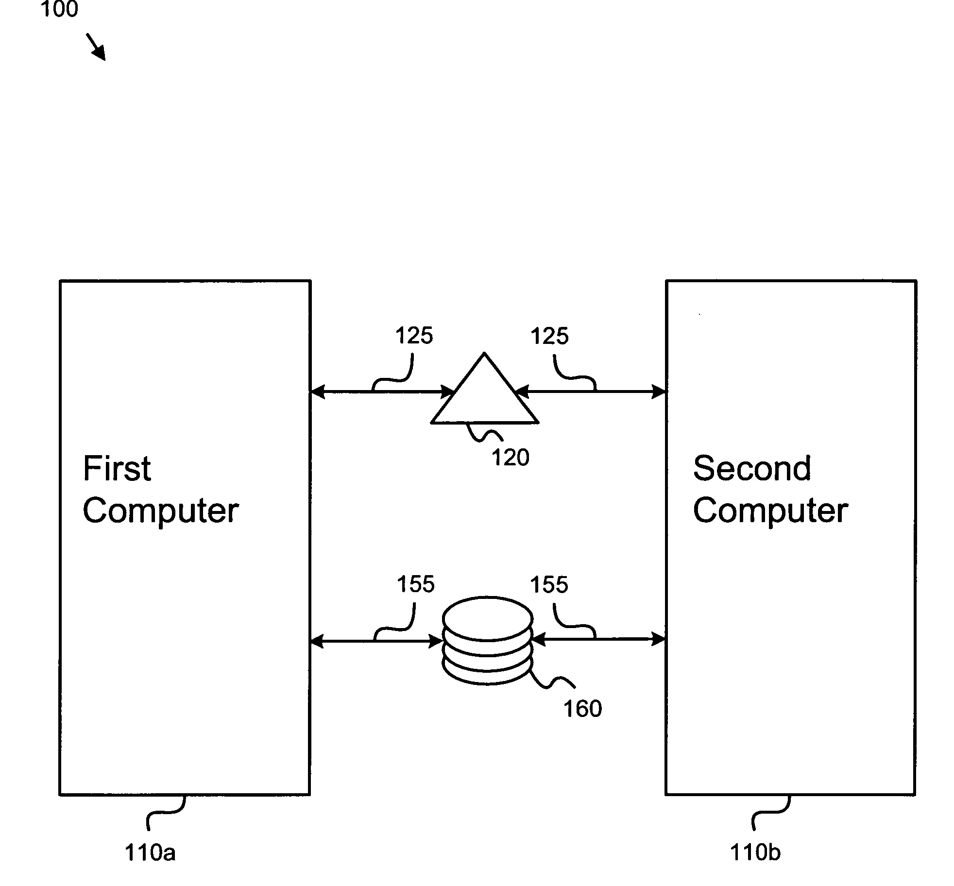
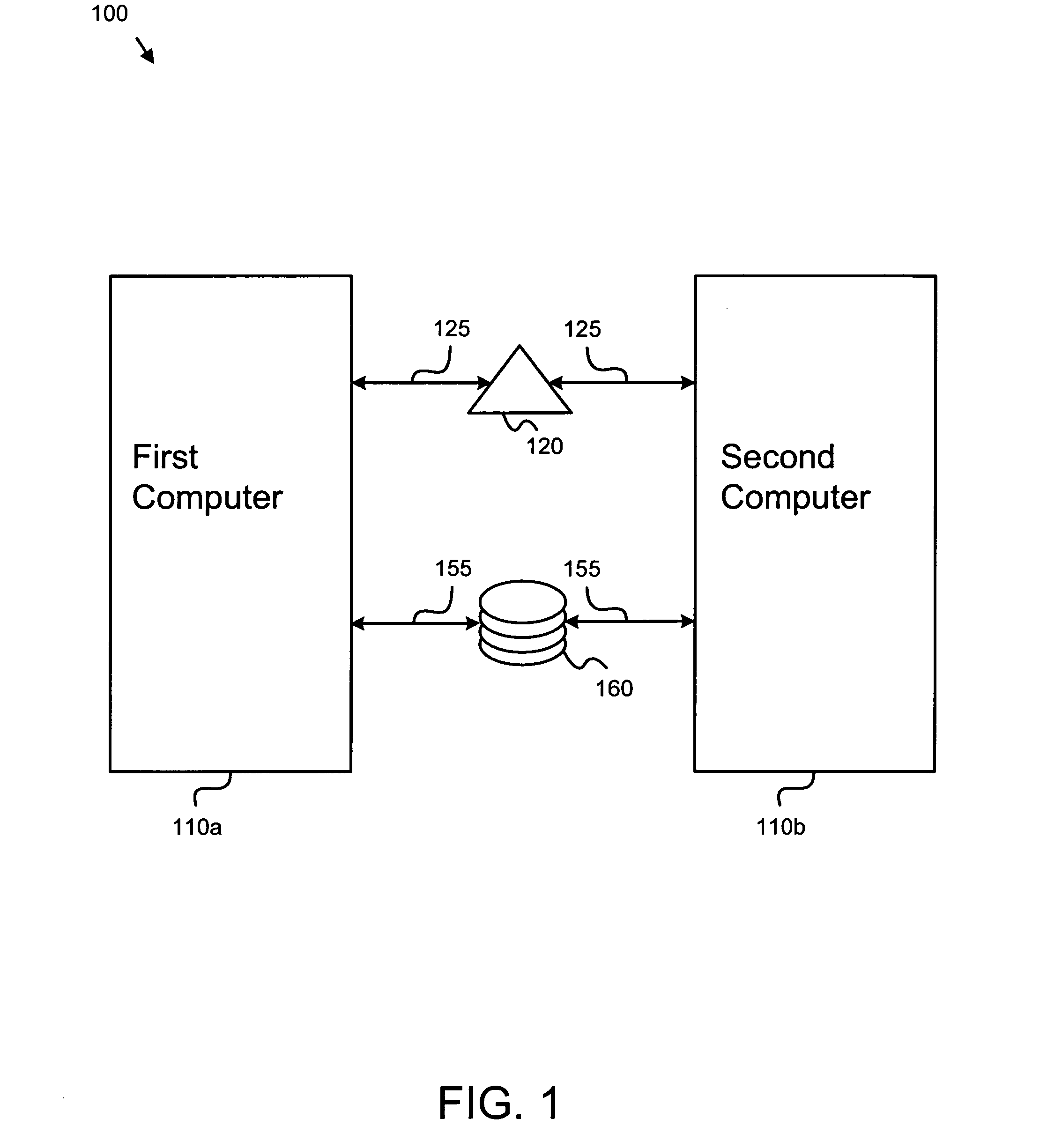
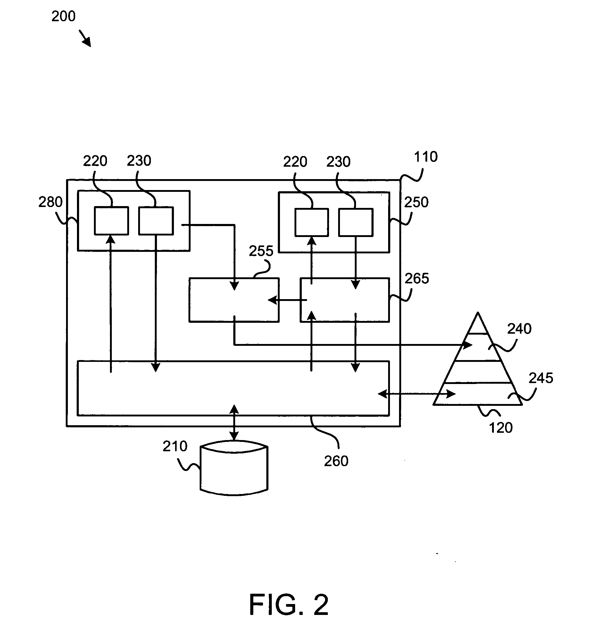
The present invention provides a peer recovery system for non-interactive transaction services programs supporting concurrent data sharing. The system includes an apparatus for peer recovery with a logic unit containing a detection module, recovery coordination module, and recovery module. The detection module detects the failure of a first computer, the recovery coordination module registers and unregisters the recovery module as the counterpart of the first computer, and the recovery module performs a recovery operation of the first computer and unlocks data resources locked by the first computer. The system also includes a shared memory controller and a disk for storing and retrieving data. The invention expeditously retrieves privately held undo log data through an authorized assumption of the failure identity associated with the failed first computer, backs out in-flight transaction updates, and releases data resources locked by the first computer. The technical effects of the invention include faster recovery times, improved data sharing, and better protection of privacy.

Problems solved by technology

Unfortunately, recovery after a computer failure can take a long time, and the process is not automatic.
In-flight transaction updates can thus remain for a long time, making locked resources unavailable to on-line transaction processing and other non-interactive jobs on active peer computers in the cluster.
In such cases, even a peer computer running on an active system cannot back out the in-flight transaction updates of the failed computer, because the peer computer cannot normally access the private undo log maintained by the failed computer.
Furthermore, the failed computer may try to restart by itself, compounding the recovery problem.

Method used


Image

  • Apparatus, system, and method for transactional peer recovery in a data sharing clustering computer system
  • Apparatus, system, and method for transactional peer recovery in a data sharing clustering computer system
  • Apparatus, system, and method for transactional peer recovery in a data sharing clustering computer system

Examples


Embodiment Construction

[0027] Many of the functional units described in this specification have been labeled as modules, in order to more particularly emphasize their implementation independence. For example, a module may be implemented as a hardware circuit comprising custom VLSI circuits or gate arrays, off-the-shelf semiconductors such as logic chips, transistors, or other discrete components. A module may also be implemented in programmable hardware devices such as field programmable gate arrays, programmable array logic, programmable logic devices or the like.

[0028] Modules may also be implemented in software for execution by various types of processors. An identified module of executable code may, for instance, comprise one or more physical or logical blocks of computer instructions which may, for instance, be organized as an object, procedure, or function. Nevertheless, the executables of an identified module need not be physically located together, but may comprise disparate instructions stored i...


PUM


Abstract

The invention provides an apparatus, system, and method for cluster-wide peer recovery in the event of a computer failure. A failure of a first computer is detected and a recovery module is registered as the first computer. In one embodiment, the recovery module is a peer computer. The recovery module retrieves a privately held undo log data through the authorized assumption of the failure identity associated with the failed first computer, backs out in-flight transaction updates of the first computer, and frees up data resources locked by the first computer.

Description

BACKGROUND OF THE INVENTION [0001] 1. Field of the Invention [0002] This invention relates to failure recovery in a computer system and more particularly relates to computer failure recovery in a transactional processing system. [0003] 2. Description of the Related Art [0004] Computer systems including transactional processing consisting of a cluster of computers logically connected to each other through a shared memory controller and sharing disks and data often support high transaction rates and high availability for on-line transaction processing (OLTP) and other applications. Clustering systems of multiple computers may execute both on-line transactions and non-interactive work. Non-interactive work, such as batch jobs including updates, can concurrently share data with on-line transaction processing. Multiple batch jobs and on-line transactions can be run against the same files. The computer system ensures data reliability and availability for batch updates while the OLTP serve...

Claims


Application Information

Patent Timeline
Patent Type & Authority Applications(United States)
IPC IPC(8): G06F11/00
CPCG06F11/1474G06F11/2046G06F11/2038G06F11/2033G06F11/1471
Inventor BRETSCHNEIDER, RONALD EDWARDDUQUETTE, MARC KENNETHEDWARDS, WILLIAM STUARTFERZIGER, RUTH LESLIEGIBSON, PETER VERLMERITHEW, LYLE LEROY JR.
Owner IBM CORP
Learn More