
Non-contact type liquid level sensor

Inactive Publication Date: 2005-11-10
YAZAKI CORP
View PDF12 Cites 12 Cited by
  • Summary
  • Abstract
  • Description
  • Claims
  • Application Information

AI Technical Summary

Benefits of technology

[0007] The invention was made in view of the problematic situations and an object thereof is to realize the stabilization of outputs from the magnetoelectric converting element by avoiding the effects of the external magnetic field onto the magnetoelectric converting element and high reliability in the result of measurement of a liquid level backed up the stabilization so realized. In addition, another object of the invention is to realize the stabilization of outputs from the magnetoelectric converting element without disturbing an electromagnetic function given to the magnetoelectric converting element by the magnet itself.
[0015] an electromagnetic shield plate that is mounted on the housing, and prevents the magnetoelectric converting elements from being affected by an external magnetic field.
[0025] According to the non-contact type liquid level sensor that is constructed as has been described above, since the electromagnetic shield plate prevents the direct effects of the external magnetic field onto the stators and the magnetoelectric converting element, only the magnetic field generated by the magnet can be applied to the magnetoelectric converting element via the stators. Consequently, a change in output from the magnetoelectric converting element can be stabilized to thereby make highly reliable the result of measurement of a liquid level in association with the movement of the float.
[0026] According to the non-contact type liquid level sensor that is constructed as has been described above, the magnetic field of the magnet is prevented from passing through the electromagnetic shield plate acting as a flux path so as not to be diffused, and is converged to the stators and the magnetoelectric converting element to thereby prevent deterioration of the output from the magnetoelectric converting element.
[0029] The non-contact type liquid level sensor according to the invention can prevent the direct effects of the external magnetic field resulting from the magnetic field generating components onto the magnetoelectric converting element by the electromagnetic shield plate, whereby the magnetic field from the magnet which rotates in response to the movement of the float can be detected with high sensitivity and high accuracy from the magnetoelectric converting element.

Problems solved by technology

However, an external magnetic field like this changes the output characteristics held by the Hall-effect IC itself and deteriorates the detection accuracy of a liquid level.
According to what is illustrated therein, when there exists no external magnetic field in the vicinity of the portion where the fuel tank is placed, an output of a predetermined sensitivity can be obtained with respect to the rotational angle of the magnet as shown by a solid line X, whereas when there exists an external magnetic field, the external magnetic field acts on the Hall-effect IC and an output therefrom changes as shown by a dotted line Y. As a result, there are caused problems that the output change with respect to the rotational angle of the magnet is small, that the detection sensitivity is deteriorated and that the result of measurement of a liquid level lacks reliability.

Method used


Image

  • Non-contact type liquid level sensor
  • Non-contact type liquid level sensor
  • Non-contact type liquid level sensor

Examples


Embodiment Construction

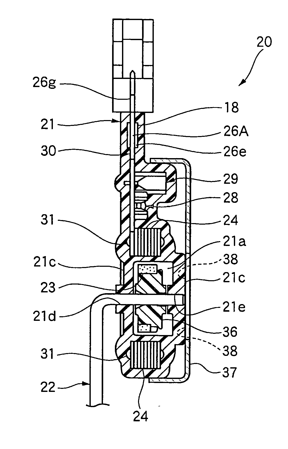
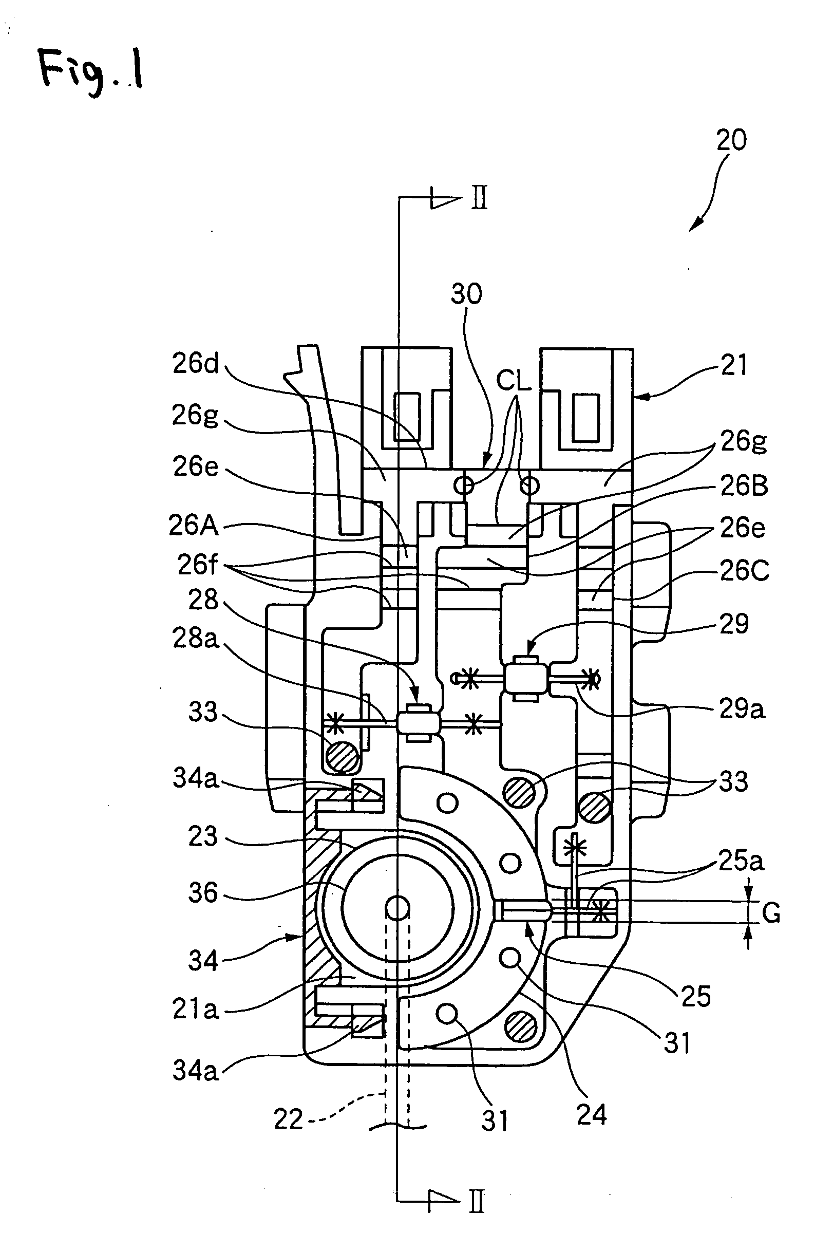
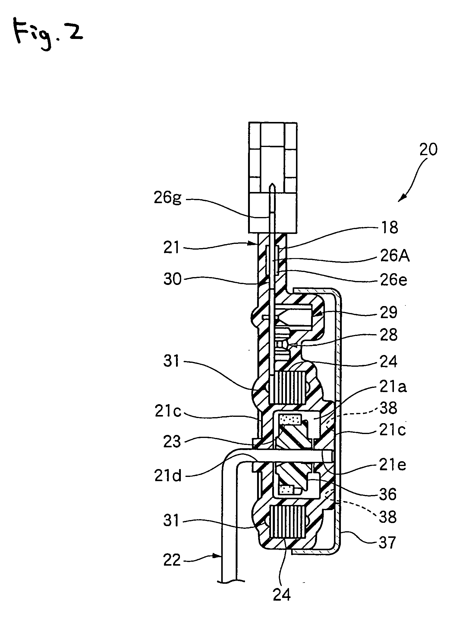
[0038] Hereinafter, an embodiment of a non-contact type liquid level sensor according to the invention will be described in detail based on the accompanying drawings. FIG. 1 is a plan view of a non-contact type liquid level sensor which is an embodiment of the invention, in which for the sake of easy understanding, a front side of a housing is deleted so as to make an inserted terminal assembly visible, and FIG. 2 is a sectional view taken along the line II-II in FIG. 1 so as to be viewed in a direction indicated by arrows at ends of the line.

[0039] As shown in FIGS. 1 and 2, in the non-contact type liquid level sensor 20, which is the embodiment of the invention, a terminal assembly 30 is insert molded in a housing 21, and almost all portions of the terminal assembly 30 excluding portions for external connection 26g are embedded in the housing 21.

[0040] The terminal assembly 30 is made up of terminals 26A, 26B, 26C, a magnetoelectric converting element 25, a resistor 28, a capaci...


PUM


Abstract

A non-contact type liquid level sensor according to the invention has an electromagnetic shield plate mounted on a housing for blocking effects from an external magnetic field onto a magnetoelectric converting element.

Description

BACKGROUND OF THE INVENTION [0001] The present invention relates to a non-contact type liquid level sensor and, more particularly, to a non-contact type liquid level sensor which can convert the motion of a float into a change in magnetic flux for detection with high accuracy and which is hence appropriate for an application to an automotive fuel tank and the like. [0002] For example, in a non-contact type liquid level sensor, which is installed in an automotive fuel tank of an automobile for detection of the volume of stored liquid fuel, an annular magnet adapted to rotate in response to the movement of a float is disposed within a frame. A Hall-effect element, which is a magnetoelectric converting element, is disposed within the same plane as a plane where the annular magnet is disposed and at a central portion of the magnet, and the Hall-effect element detects a change in magnetic flux density due to the rotating magnet and then converts the change so detected into an electric si...

Claims


Application Information

Patent Timeline
IPC IPC(8): G01F23/00G01F23/38G01F23/52
CPCG01F23/38
Inventor FUKUHARA, TOSHIAKITANAKA, KENICHI
Owner YAZAKI CORP
Learn More