A system and method for providing an RFID transaction device

a technology of a transaction device and a transaction device, which is applied in the field of system and method of providing a transaction device, can solve the problems of form factors that are still susceptible to being lost or misplaced by the fob owner, and key chains or fob form factors are sometimes inconvenient, so as to promote the constricting action of the loop around the article, relax the tension on the band, and reduce the size of the loop to the effect of constricting the articl

Inactive Publication Date: 2005-11-10
LIBERTY PEAK VENTURES LLC
View PDF99 Cites 50 Cited by
  • Summary
  • Abstract
  • Description
  • Claims
  • Application Information

AI Technical Summary

Benefits of technology

[0010] In another exemplary embodiment, the attachment apparatus is an elastic band affixed to the RFID module carrier housing that is used to attach the carrier housing to a consumer's person, clothing, or any article carried by the consumer. The elastic band includes a first band end affixed to the carrier housing and the second band end affixed to a second opposing end of the carrier housing such that the band forms a loop including the carrier housing. Since the band is elastic the size of the loop may be adjusted by placing tension on the band to enlarge the loop permitting the consumer to insert an article between the elastic band and the carrier housing. Once the tension on the band is relaxed, the band surrounds and grips the article, affixing the carrier housing to the consumer, or to an article worn or carried by the consumer.
[0011] In yet another exemplary embodiment, the attachment apparatus includes an attachment apparatus housing having a torsion spring attached to a band for retracting a portion of the band into the attachment housing. The band is attached to the spring at a first band end and attached to the carrier housing at a second opposing band end so that a loop is formed between the band and the carrier housing. The size of the loop is adjusted by applying a force to the first band end attached to the torsion spring to remove a portion of the band from the attachment housing. The carrier housing is attached to an article by inserting the article in the loop and permitting the spring to place a force on the band to retract the band into the carrier housing, thereby reducing the size of the loop to constrict over the article.
[0012] In still another embodiment, the attachment apparatus includes a first string attached to a first end of the carrier housing and a second string attached to a second opposing end of the carrier housing. The first and second strings may be placed in proximity one to the other near the distal ends of the strings using a slideable string fastener, such that the first and second strings form a loop between the fastener and the carrier housing. The string fastener is operable to adjust the size of the loop for inserting an article in the loop between the fastener and the carrier housing. The carrier housing is affixed to the consumer, or to an article carried or worn by the consumer by sliding the fastener along the first and second string in proximity to the article, the fastener thereby promoting the constricting action of the loop around the article.
[0013] In still another embodiment, the attachment apparatus is a single continuous string where the first end of the string is attached to a first portion of the RFID module carrier housing and the second end of the string is attached to a second opposing portion of the RFID module carrier housing, such that the string forms a loop including the carrier housing. The continuous string is pinched along the loop by a string fastener forming a first smaller loop away from the carrier housing between the fastener and the carrier housing and a second larger loop. The string fastener is slideable for adjusting the size of the larger loop. The fastener is slid along the string and nearer to the carrier housing, thereby reducing the circumference of the larger loop permitting the loop to be constricted around an article. The constricting action secures the housing to a consumer, consumer's clothing, or to an apparatus carried by the consumer, as before.

Problems solved by technology

Key chain or fob form factors have a major drawback in that the form factors are still susceptible to being lost or misplaced by the fob owner.
Additionally, the key chain or fob form factors are sometimes inconvenient in that the consumer must still handle the form factor to present it for transaction completion.

Method used


Image

  • A system and method for providing an RFID transaction device
  • A system and method for providing an RFID transaction device
  • A system and method for providing an RFID transaction device

Examples


Embodiment Construction

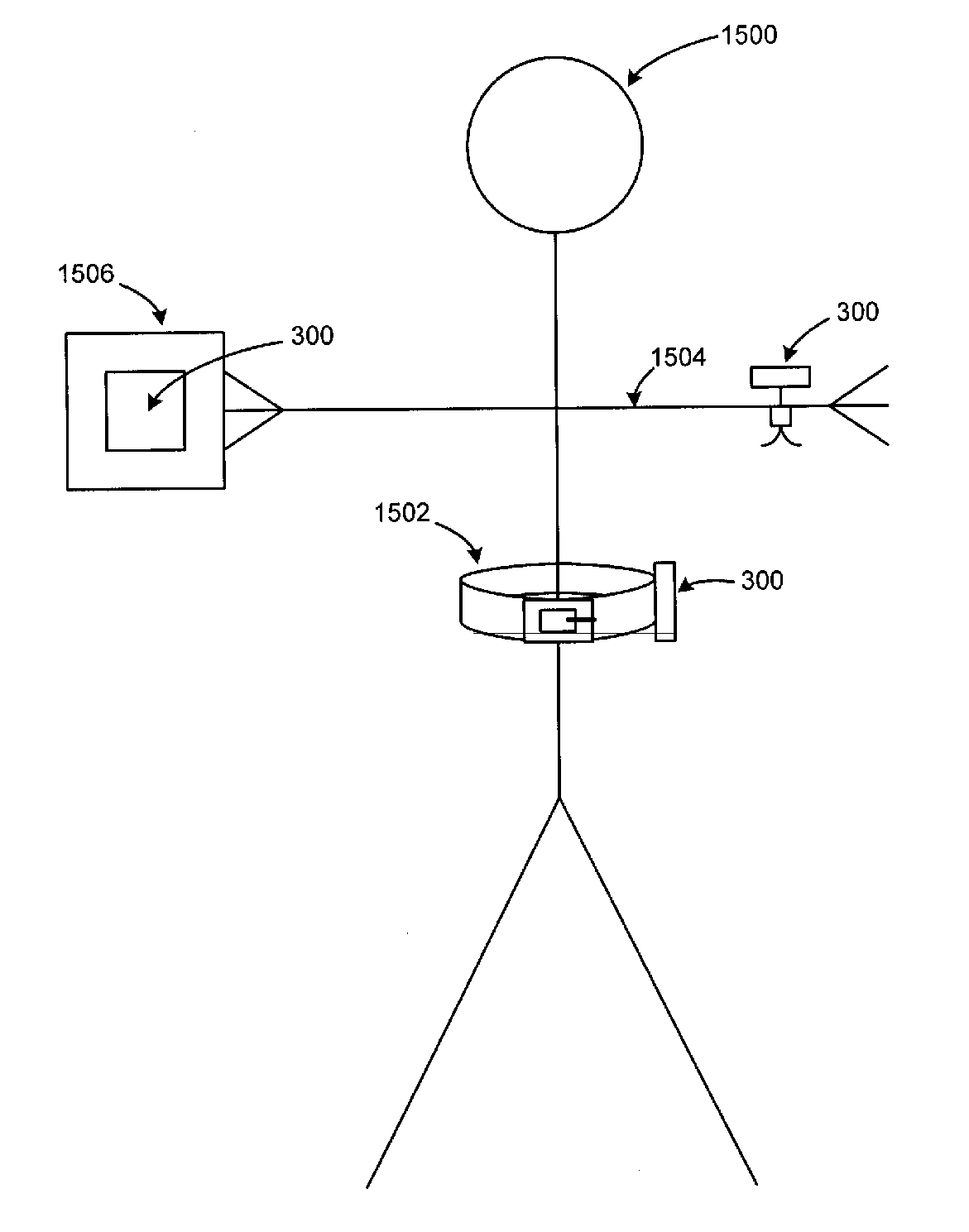
[0038] The present invention includes a system and method for securing an RFID transaction device to an article. The RFID transaction device in accordance with this invention is operable to complete a transaction in a contactless environment using RFID technology. An exemplary transaction device useful with the invention includes a conventional RFID operable transponder system capable of receiving an interrogation signal and providing RFID transponder system identifying data for transaction completion. As used herein, the circuitry supporting the RFID operation of the transaction is called “RFID module” for consistency.

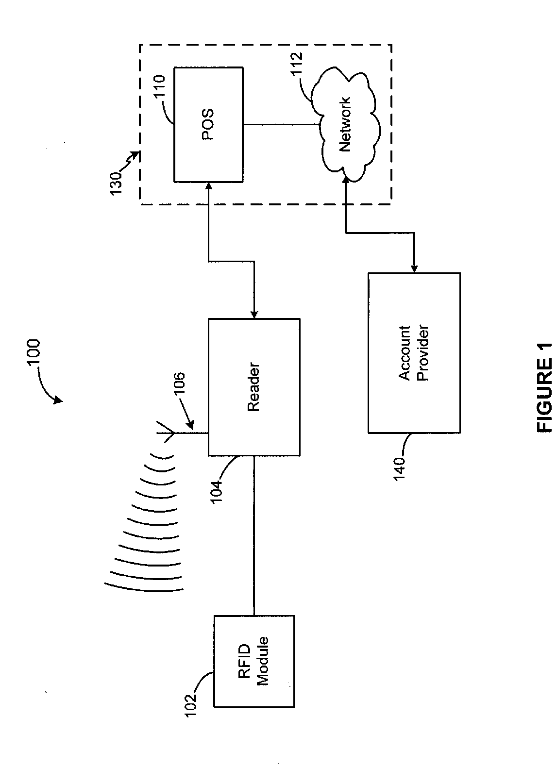
[0039]FIG. 1 illustrates an exemplary RFID transaction completion system 100 wherein exemplary components for RFID transaction completion are depicted. System 100 includes an RFID module 102 in RF communication with an RFID reader 104 via an antenna 106. RFID reader 104 is in communication with a merchant system 130 via point-of-sale device 110. Merchant system 130 i...


PUM


Abstract

A system and method for attaching a Radio Frequency operable transaction device to an article using various attachment apparatus are disclosed. The invention includes attaching a transaction device to an article using apparatuses comprised of bands, clips, clamps, drawstrings, and adhesives. The present invention allows for the securing of an RF transaction device (e.g., a payment fob) to a consumer's person thereby enabling a transaction to be completed without the need for the consumer to manually present the transaction device.

Description

CROSS-REFERENCE TO RELATED APPLICATIONS [0001] This application is a continuation-in-part of, and claims priority to, U.S. application Ser. No. 10 / 746,781, entitled “A SYSTEM AND METHOD FOR MANUFACTURING A PUNCH-OUT RFID TRANSACTION DEVICE,” filed Dec. 24, 2003. This application is also a continuation-in-part of, and claims priority to, U.S. patent application Ser. No. 10 / 192,488, entitled “SYSTEM AND METHOD FOR PAYMENT USING RADIO FREQUENCY IDENTIFICATION IN CONTACT AND CONTACTLESS TRANSACTIONS,” filed Jul. 9, 2002 (which itself claims priority to U.S. Provisional Patent Application No. 60 / 304,216, filed Jul. 10, 2001). The application is also a continuation-in-part of and claims priority, to U.S. patent application Ser. No. 10 / 340,352, entitled “SYSTEM AND METHOD FOR INCENTING PAYMENT USING RADIO FREQUENCY IDENTIFICATION IN CONTACT AND CONTACTLESS TRANSACTIONS,” filed Jan. 10, 2003 (which itself claims priority to U.S. Provisional Patent Application No. 60 / 396,577, filed Jul. 16, ...

Claims


Application Information

Patent Timeline
Patent Type & Authority Applications(United States)
IPC IPC(8): G08B13/14G08B13/24
CPCG08B13/2434G08B13/2417
Inventor BONALLE, DAVID SFRANCOLINI, GAIL AING, SAMANTHA SKUNIAN, DANIELLENULLE, DANIELLE R
Owner LIBERTY PEAK VENTURES LLC
Why Eureka
Try Eureka