Image-based object detection apparatus and method

a technology of object detection and object detection, applied in the field of image-based object detection apparatus and method, can solve the problems of difficult separation of background optical flow of stationary objects from optical flow of stationary objects, inability to accurately detect stationary objects, and difficulty in accurately detecting moving objects in images. to achieve the effect of improving the accuracy of object detection

Inactive Publication Date: 2005-11-10
HONDA MOTOR CO LTD
View PDF8 Cites 35 Cited by
  • Summary
  • Abstract
  • Description
  • Claims
  • Application Information

AI Technical Summary

Benefits of technology

[0006] According to the present invention, an object detection apparatus for detecting objects based on visual images captured by a self-moving unit is provided. The apparatus performs global area image process for recognizing a motion field of the entire view associated to the self-motion and segregating an area incoherent with said motion field, and local area image process for calculating local flow information in the visual images in parallel. The apparatus refers to results of both processes mutually to improve the accuracy of object detection.

Problems solved by technology

However, when an imaging device for capturing images is moving (for example, when the imaging device is mounted onto an automobile or the like), it would be difficult to detect the moving object in the image accurately because some optical flows associated to the self-motion of the device is generated in the image.
However, when a stationary object on a stationary background is observed from a self-moving unit, it is difficult to segregate optical flows of the stationary object from that of the background.
In this case, since the stationary object on the stationary background is recognized as a part of the background, optical flows are not emphasized and therefore the stationary object cannot be detected accurately.

Method used


Image

  • Image-based object detection apparatus and method
  • Image-based object detection apparatus and method
  • Image-based object detection apparatus and method

Examples


first embodiment

of the Invention

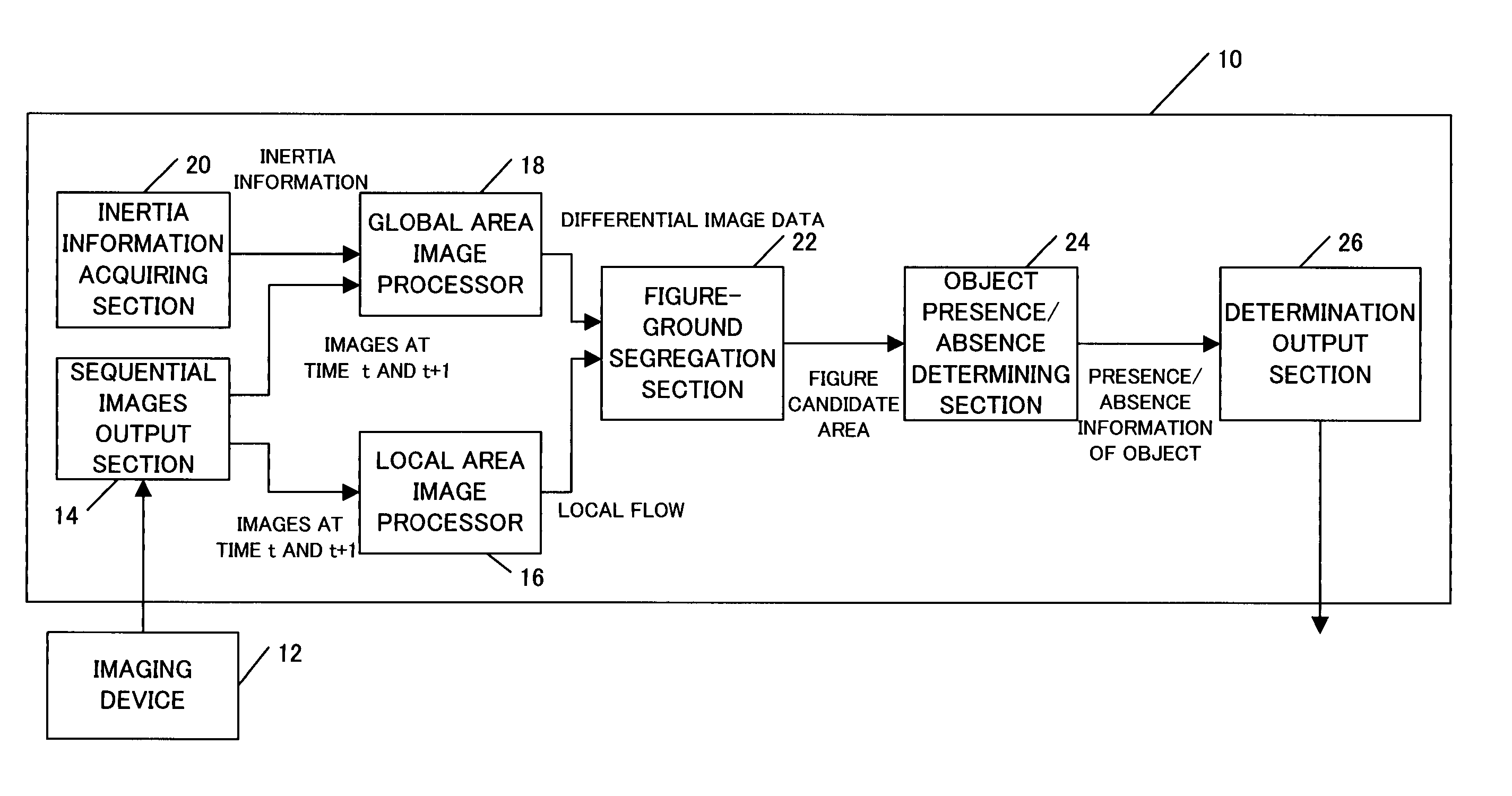
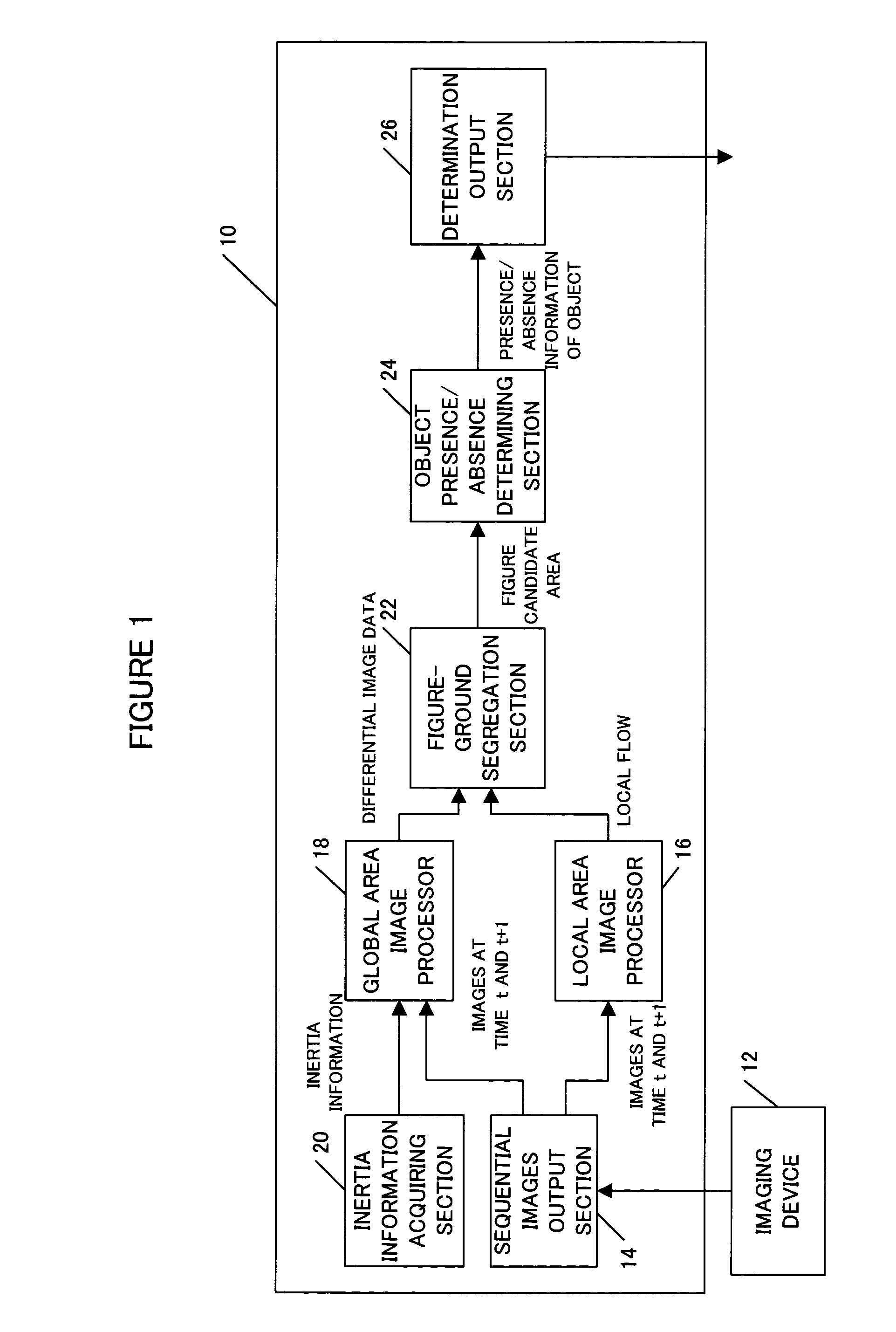
[0043]FIG. 1 shows a block diagram of an object detection apparatus according to the first embodiment of the invention. The object detection apparatus 10 receives sequential images in the direction of travel which are captured at predetermined time intervals by an imaging device 12, such as a CCD camera, mounted on a mobile unit such as an autonomous traveling vehicle. The device 10 then determines a presence / absence of an object in the image and outputs a determination result. The result signal may be supplied to a motor or a steering wheel of the mobile unit to steer around the object blocking the pass of the mobile unit. Alternatively, the result signal may be notified to passengers on the mobile unit like an autonomous vehicle or to external to the mobile unit.

[0044] The object detection apparatus 10 may be implemented by, for example, a microcomputer having at least a CPU for executing various computations, a memory for temporarily storing computation results, ...

second embodiment

of the Invention

[0074]FIG. 9 is a block diagram of an object detection apparatus 100 according to second embodiment of the invention. A sequential images output section 114, a local area image processor 116, an inertia information acquiring section 120, an object presence / absence determining section 124 and a determination output section 126 are same with corresponding function blocks of the first embodiment. Process in a global area image processor 118 and a figure-ground segregation section 122 is different from the corresponding process in the first embodiment. In contrast to the first embodiment, there is feedback from the figure-ground segregation section 122 to the global area image processor 118. Therefore, only processes in the global area image processor 118 and the figure-ground segregation section 122 will be described below with reference to flowcharts in FIG. 10.

[0075] Process in steps S130 to S134 is same with steps S50 to S54 in FIG. 6. Global flows estimated in step...

third embodiment

of the Invention

[0084] In this embodiment, a mobile unit carrying an imaging device 12 travels an environment in advance for detecting objects, captures images in the direction of motion and constructs a self-motion predictive space described below (hereinafter this process is referred to as “learning”.) When the object detection is executed, past image and present image are projected onto the self-motion predictive space and reconstruct them to create a predictive image.

[0085]FIG. 12 is a block diagram showing an overall configuration of an object detection apparatus 200 according to the third embodiment. Except for a global area image processor 218, process in each corresponding functional block is same with those of the object detection apparatus 10 according to the first embodiment shown in FIG. 1. Hereinafter process in the global area image processor 218 will be described with reference to FIGS. 13 and 14.

[0086]FIG. 13 is a flowchart in learning process. The global area imag...


PUM


Abstract

An object detection apparatus and method capable of detecting objects based on visual images captured by a self-moving unit. A sequential images output section makes a train of a first input image and a second input image sequential to the first input image and outputs said train. A local area image processor calculates local flows based on said first input image and said second input image. An inertia information acquiring section measures self-motion of the unit to calculate inertia information thereof. A global area image processor uses said inertia information to estimate global flow, which is a motion field of the entire view associated to the self-motion, using said global flow and said first input image and creates a predictive image of said second input image. The global area image processor then calculates differential image data, which is a difference between said predictive image and said second input image. A figure-ground segregation section uses said differential image data to refine said local flows and compares the refined local flows with a predetermined threshold value to extract a figure candidate area, which is the area having a high probability of an object existing in the input image. An object presence/absence determination section determines presence/absence of objects in said figure candidate area.

Description

TECHNICAL FIELD [0001] The present invention relates to an image-based object detection apparatus and method, and more particularly to an object detection apparatus and method capable of detecting objects based on visual images captured by a self-moving unit. BACKGROUND OF THE INVENTION [0002] Some techniques for detecting objects in captured images based on visual images are known in the art. For example, there is a method for calculating optical flows from captured sequential images and detecting a part of image corresponding to an object within area having same motion components. Since this can easily detect a moving object in the image, many object detection apparatus employs such method (for example, Japanese unexamined patent publication (Kokai) No. 07-249127) [0003] However, when an imaging device for capturing images is moving (for example, when the imaging device is mounted onto an automobile or the like), it would be difficult to detect the moving object in the image accur...

Claims


Application Information

Patent Timeline
Patent Type & Authority Applications(United States)
IPC IPC(8): B60R1/00G06T1/00G06T7/20H04N7/18
CPCG06T7/0002G06T7/0008G06T7/2066G06T7/2053G06T7/2006G06T7/215G06T7/254G06T7/269
Inventor TSUJINO, HIROSHIKONDO, HIROSHINAGAI, SHINICHIAKATSUKA, KOJIMIURA, ATSUSHI
Owner HONDA MOTOR CO LTD
Why Eureka
Try Eureka