

Zoom lens system and image capture apparatus having the same
- Summary
- Abstract
- Description
- Claims
- Application Information
AI Technical Summary
Benefits of technology
Problems solved by technology
Method used
Image

Examples
numerical example 1
[0057] Numerical Example 1
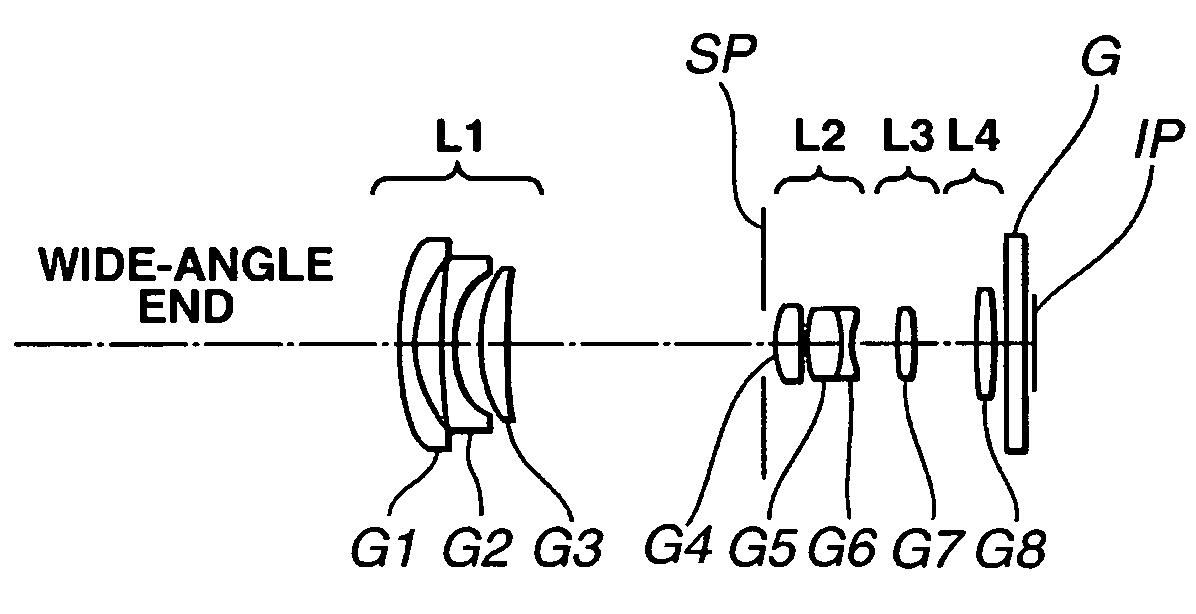
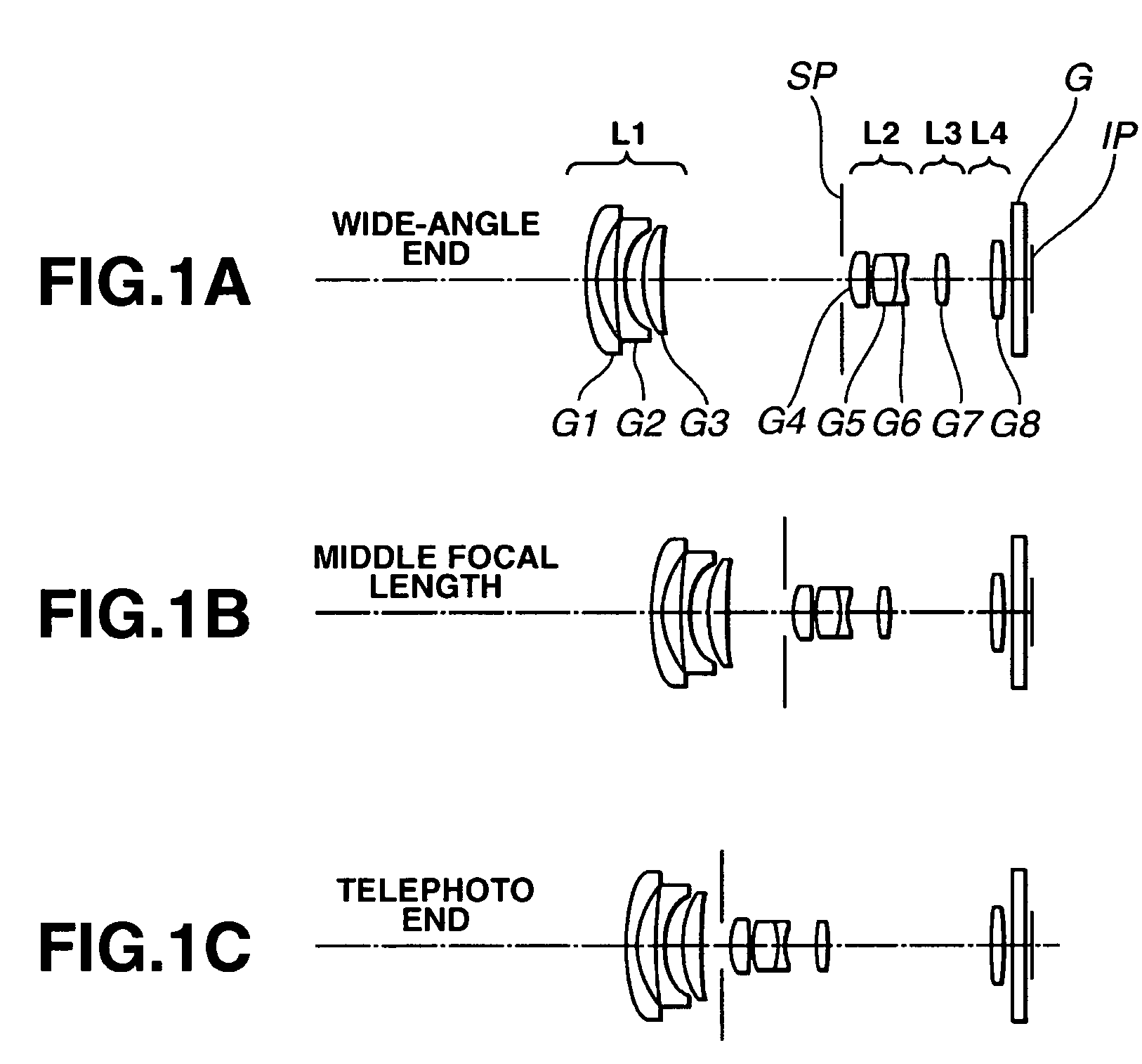
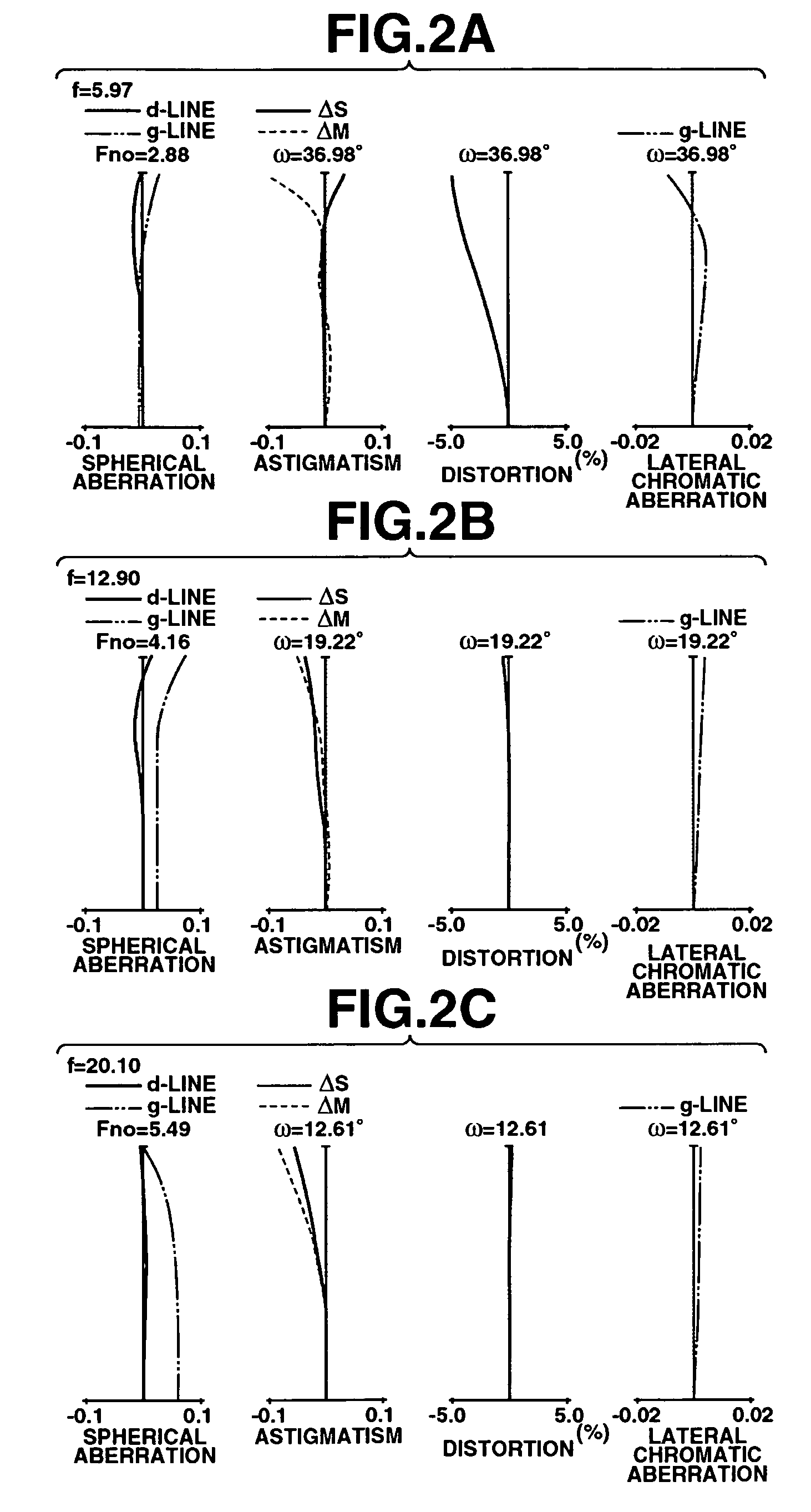
f = 5.97 − 20.10Fno = 2.88 − 5.502ω = 74.6 − 25.5 R1 = 23.157 D1 = 1.70N1 = 1.853000ν1 = 40.9 *R2 = 10.478 D2 = 2.31 R3 = 62.965 D3 = 1.00N2 = 1.882997ν2 = 40.8 R4 = 8.497 D4 = 2.64 R5 = 13.300 D5 = 2.50N3 = 1.846660ν3 = 23.9 R6 = 52.650 D6 = Variable R7 = Stop D7 = 0.80 R8 = 8.233 D8 = 2.60N4 = 1.516330ν4 = 64.1 R9 = −49.857 D9 = 0.43*R10 = 10.259D10 = 3.37N5 = 1.730770ν5 = 40.5 R11 = −11.006D11 = 0.70N6 = 1.728250ν6 = 28.5 R12 = 5.517D12 = Variable R13 = 33.423D13 = 1.30N7 = 1.487490ν7 = 70.2 R14 = −33.423D14 = Variable R15 = 23.500D15 = 1.80N8 = 1.487490ν8 = 70.2 R16 = −45.645D16 = 1.20 R17 = ∞D17 = 1.50N9 = 1.516330ν9 = 64.1 R18 = ∞Focal Length5.9712.9020.10Variable Space D624.097.622.56D124.404.274.12D145.8513.9922.39Aspheric Coefficients R2:k = −1.04742e + 00A = 0B = 2.90470e − 05C = −9.00594e − 07D = −3.40817e − 09E = −3.22499e − 11R10:k = −1.03518e + 00A = 0B = −1.15123e − 04C = −3.90010e − 06D = −9.83696e − 08E = −6.11202e − 10
numerical example 2
[0058] Numerical Example 2
f = 5.99 − 20.10Fno = 2.88 − 5.502ω = 74.4 − 25.5 R1 = 24.965 D1 = 1.70N1 = 1.870000ν1 = 40.0 *R2 = 10.628 D2 = 2.32 R3 = 57.663 D3 = 1.00N2 = 1.882997ν2 = 40.8 R4 = 8.590 D4 = 2.63 R5 = 13.491 D5 = 2.50N3 = 1.846660ν3 = 23.9 R6 = 57.555 D6 = Variable R7 = Stop D7 = 0.80 R8 = 7.853 D8 = 2.50N4 = 1.516330ν4 = 64.1 R9 = −55.428 D9 = 0.62*R10 = 10.260D10 = 3.26N5 = 1.730770ν5 = 40.5 R11 = −11.083D11 = 0.70N6 = 1.728250ν6 = 28.5 R12 = 5.406D12 = Variable R13 = 28.838D13 = 1.30N7 = 1.487490ν7 = 70.2 R14 = −41.508D14 = Variable R15 = 23.500D15 = 1.80N8 = 1.516330ν8 = 64.1 R16 = −46.053D16 = 0.70 R17 = ∞D17 = 1.50N9 = 1.516330ν9 = 64.1 R18 = ∞Focal Length5.9913.2820.10Variable Space D624.497.192.55D124.763.784.00D145.9214.7122.31
[0059] Aspheric Coefficients
R2:k = −1.09983e + 00A = 0B = 3.44778e − 05C = −1.09453e − 06D = −1.35822e − 09E = −5.58071e − 11R10:k = −1.29070e + 00A = 0B = −1.22161e − 04C = −5.18865e − 06D = −1.20943e − 07E = −6.56441e − 10
numerical example 3
[0060] Numerical Example 3
f = 5.99 − 21.08Fno = 2.88 − 5.502ω = 74.4 − 24.4 R1 = 25.592 D1 = 1.70N1 = 1.883000ν1 = 40.8 *R2 = 10.914 D2 = 2.32 R3 = 48.244 D3 = 1.00N2 = 1.882997ν2 = 40.8 R4 = 8.638 D4 = 2.68 R5 = 13.529 D5 = 2.50N3 = 1.846660ν3 = 23.9 R6 = 53.851 D6 = Variable R7 = Stop D7 = 0.80 R8 = 7.868 D8 = 2.50N4 = 1.516330ν4 = 64.1 R9 = −57.136 D9 = 0.53*R10 = 10.270D10 = 3.15N5 = 1.730770ν5 = 40.5 R11 = −12.726D11 = 0.70N6 = 1.728250ν6 = 28.5 R12 = 5.420D12 = Variable R13 = 30.158D13 = 1.20N7 = 1.487490ν7 = 70.2 R14 = −46.523D14 = Variable R15 = 23.500D15 = 1.70N8 = 1.487490ν8 = 70.2 R16 = −48.994D16 = 1.20 R17 = ∞D17 = 1.50N9 = 1.516330ν9 = 64.2 R18 = ∞Focal Length5.9913.6921.08Variable Space D627.087.862.84D125.574.234.09D145.8515.3723.71
[0061] Aspheric Coefficients
R2:k = −1.00708e + 00A = 0B = 2.13351e − 05C = −1.12460e − 06D = 2.03412e − 09E = −3.80041e − 11R10:k = −1.20721e + 00A = 0B = −1.18374e − 04C = −4.79729e − 06D = −1.09044e − 07E = −7.59094e − 10
[0062]
TABLE 1...
PUM
 Abstract
Description
Claims
Application Information