
RF wireless permanently mounted searchlight

a permanent mounting and wireless technology, applied in the field of searchlights, can solve the problem of not disclosing the control of such a remote/wireless light system using a wireless digitally encoded modulation signal, and achieve the effect of reducing interference, minimizing fm interference, and increasing the potential market for your company's searchligh

Inactive Publication Date: 2005-11-10
XYLEM IP HLDG
View PDF22 Cites 63 Cited by
  • Summary
  • Abstract
  • Description
  • Claims
  • Application Information

AI Technical Summary

Benefits of technology

[0011] One advantage of the RF wireless searchlight according to the present invention is that the FM wireless digitally encoded modulation wireless signal, especially at a frequency of 434 Mhz, eliminates interferences otherwise caused if an AM signal was used in relation to noise generated from driver motors moving the search lamp; minimizes FM interferences in relation to signals generated from various other devices otherwise broadcasting typically in a range of 303-390 Mhz, including garage door openers, lighting controls and ceiling fan controls; is a worldwide accepted frequency, for example, in the U.S., Europe and Canada, increasing the potential marketplace for your company's searchlight as a whole. Also FM is resistant to on-vehicle generator and engine electrical noise. It is omnidirectional so there are no line-of-sight issues like those using directional antenna signals. For example, in one known searchlight using an AM-based RF wireless system the AM noise and interference from the driver motor moving the search lamp may actually prevent the stopping of the search lamp once it is set in motion.

Problems solved by technology

However, these patents do not disclose controlling such a remote / wireless light system using a wireless digitally encoded modulation signal.

Method used


Image

  • RF wireless permanently mounted searchlight
  • RF wireless permanently mounted searchlight
  • RF wireless permanently mounted searchlight

Examples


Embodiment Construction

FIG. 1: The Basic Invention

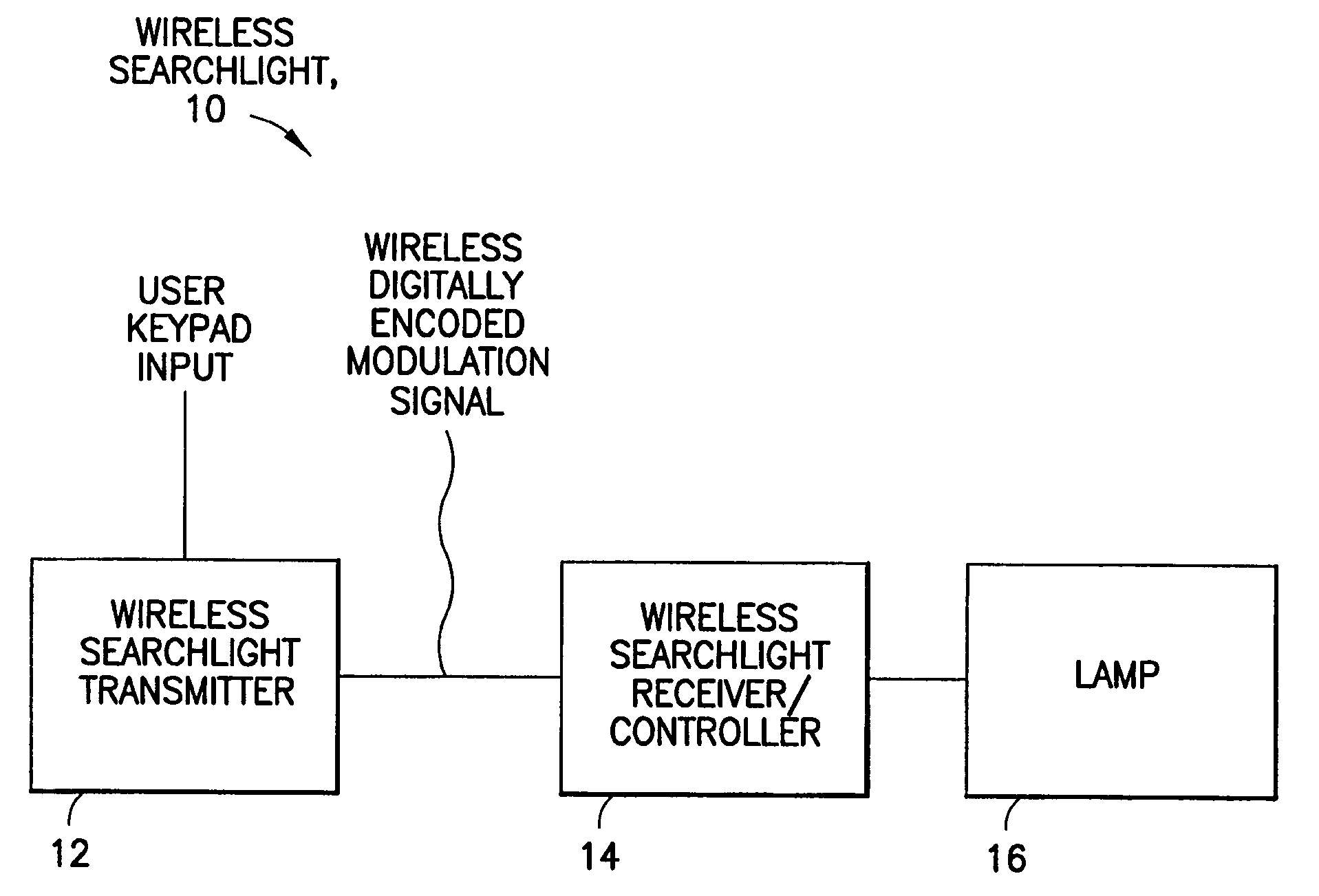
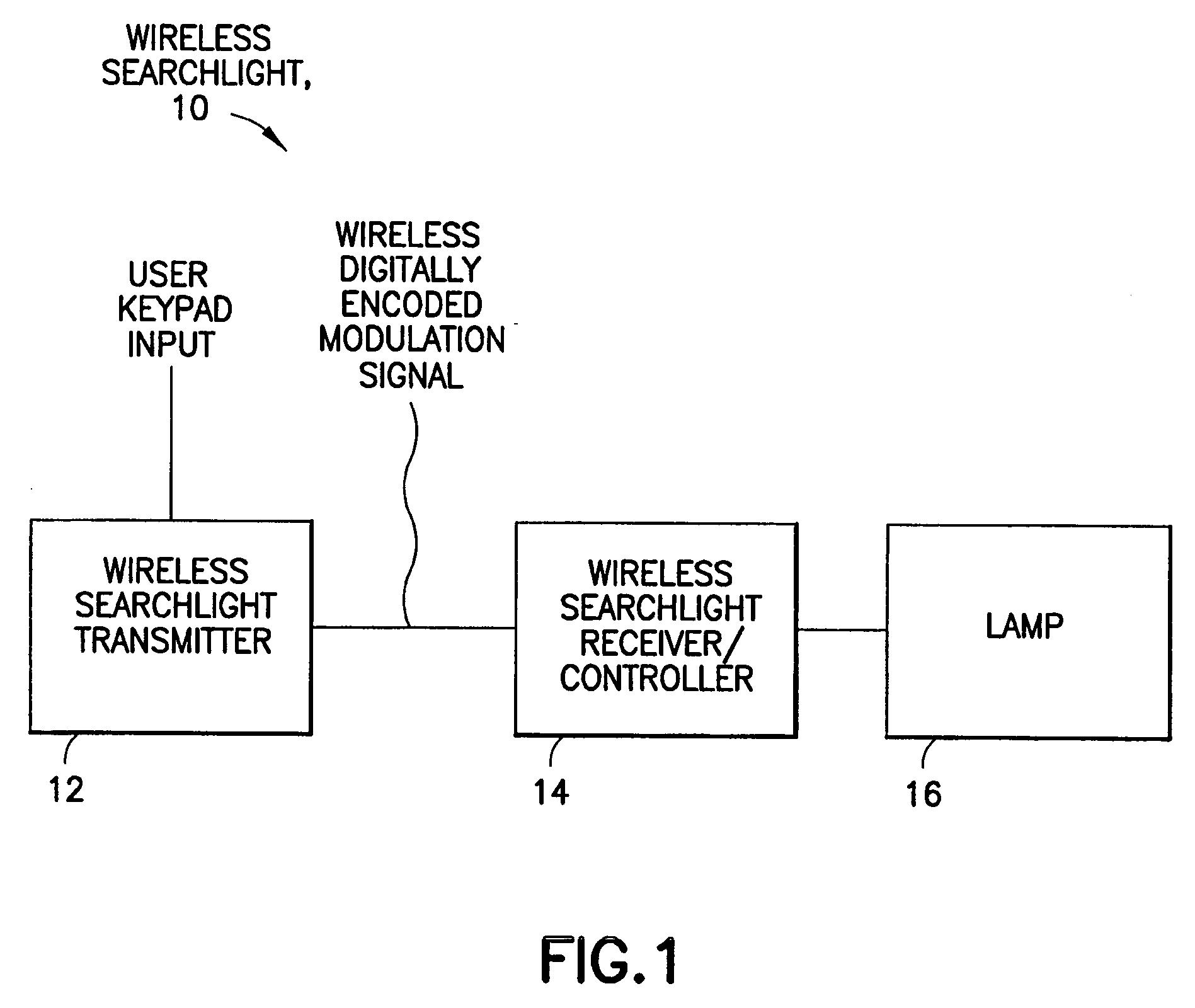
[0022]FIG. 1 shows a new and unique wireless searchlight 10 according to the present invention, featuring a wireless searchlight transmitter 12, a wireless searchlight receiver / controller 14 and a searchlight or lamp 16. In operation, the wireless searchlight transmitter 12 responds to user inputs, and provides a transmitter control signal in the form of a wireless digitally encoded modulation signal to the wireless searchlight receiver / controller 14; and the wireless searchlight receiver / controller 14 responds to this transmitter control signal and provides signals for controlling the functionality of the searchlight or lamp 16. The user inputs may be in the form of user keypad inputs, as well as other suitable user inputs, including voice and / or other audio commands. The scope of the invention is not intended to be limited to the manner in which the user provides the inputs too the transmitter. The wireless digitally encoded modulation signal contains in...


PUM


Abstract

The invention provides apparatus for controlling a search lamp using a wireless transmitter and receiver. The transmitter responds to user inputs by providing a wireless digitally encoded modulation signal containing information indicating at least one operation in a set of operations the search lamp is able to perform. The receiver responds to the wireless digitally encoded modulation signal by providing a control signal for controlling the functionality of the search lamp. The functionality may include, for example, moving the search lamp left / right and / or up / down, a sweep on / off @ ±45 degrees; X / Y / Z movement (Z when motors run simultaneously); Diagonal sweep (motors run simultaneously); Fast / Slow sweep (50% / 100%). The transmitter and receiver are programmable to communicate on a unique 16 bit digital code setting that provides about 65K different code settings, which may also include a random code setting.

Description

CROSS REFERENCE TO RELATED APPLICATION [0001] This application claims benefit to provisional patent application Ser. No. 60 / 533,353, filed Dec.29, 2003, which is hereby incorporated by reference in its entirety.BACKGROUND OF THE INVENTION [0002] 1. Field Of Invention [0003] The present invention relates to a searchlight; and more particularly to a wireless permanently mounted searchlight. [0004] 2. Description of Related Art [0005] Many different types and kinds of remotely controlled lights and searchlights are known in the art. By way of example, U.S. Pat. No. 4,779,168 discloses a remote / wireless light system with battery power and includes a transmitter / microprocessor, a receiver / microprocessor, batteries, lamp and positioning device, while U.S. Pat. Nos. 5,490,046 and 5,673,989 disclose a wireless portable searchlight having motors and a battery. However, these patents do not disclose controlling such a remote / wireless light system using a wireless digitally encoded modulation ...

Claims


Application Information

Patent Timeline
Patent Type & Authority Applications(United States)
IPC IPC(8): F21V33/00H05B37/02
CPCH05B37/0272B60Q1/245H05B47/19
Inventor NAVAL, RUFINO U.LEE, RICHARD W.MCDONOUGH, WILLIAM B.
Owner XYLEM IP HLDG
Learn More