
Multifiber ferrule

a multi-fiber ferrule and fiber technology, applied in the field of ferrules, can solve the problems of reducing the area of the mating surface of the ferrule, affecting and affecting the appearance of the component, so as to improve the design of the ferrule and reduce the area of the mating surfa

Inactive Publication Date: 2005-11-10
TE CONNECTIVITY CORP
View PDF8 Cites 12 Cited by
  • Summary
  • Abstract
  • Description
  • Claims
  • Application Information

AI Technical Summary

Benefits of technology

[0010] Since the mating surface is reduced to a small area, better physical contact can be achieved. Specifically, the reduced mating surface area tends to be more forgiving of angular misalignment. A smaller mating surface is also less likely to encounter irregularities which may impede physical contact. Finally, by reducing the mating surface, the force required to deform it is reduced as well.

Problems solved by technology

Although effective in handling a larger number of fibers, MT ferrules have traditionally suffered from problems establishing good physical contact among all the fibers.
The applicants have identified several causes for the difficulties in establishing physical contact with an MT ferrule, all of which involve the larger mating surface of the MT ferrule.
One of the more significant difficulties arises with angular misalignment between the mating surface and the optical component to which the ferrule is intended to mate.
More specifically, since angular misalignment between the mating surface and the optical component will cause the edge of the mating surface to contact the component first, a gap will result between the center of the mating surface and the component.
Since the fiber ends are typically in the center of the mating surface, angular misalignment will necessarily separate the fibers' ends from the optical component and make physical contact more difficult.
Another reason why physical contact is more difficult in MT ferrules is the fact that a large mating surface is more difficult to deform to achieve physical contact.
As a surface becomes larger, it becomes more difficult to deform.
Often the required force is beyond the ability of the connector or interconnection system to deliver.
Yet another problem with establishing physical contact with a larger mating surface is the greater probability of encountering irregularities on the mating surface.
Such irregularities may prevent intimate contact with the other optical component and, thus, diminish the physical contact between the mating fiber ends.

Method used


Image

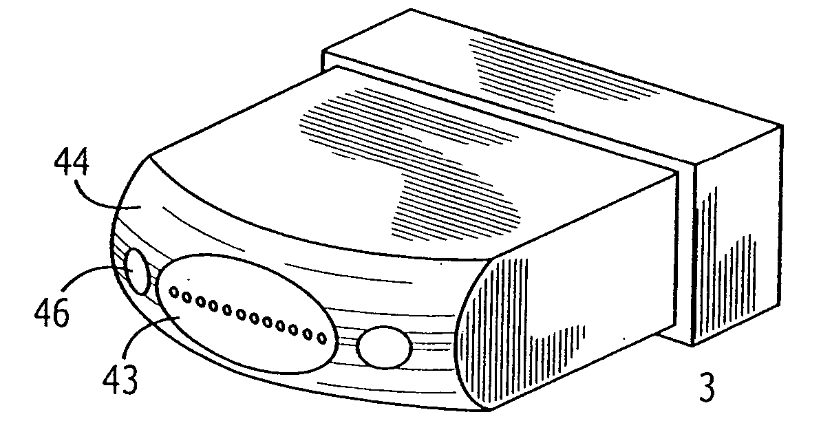
  • Multifiber ferrule
  • Multifiber ferrule
  • Multifiber ferrule

Examples


Embodiment Construction

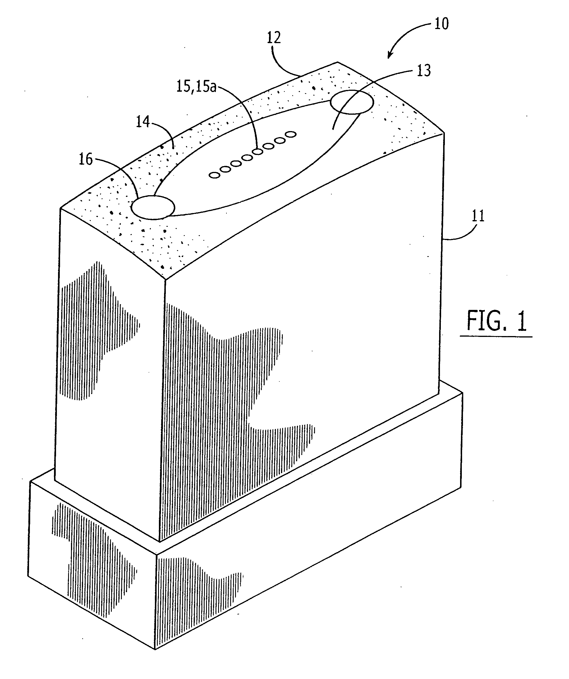
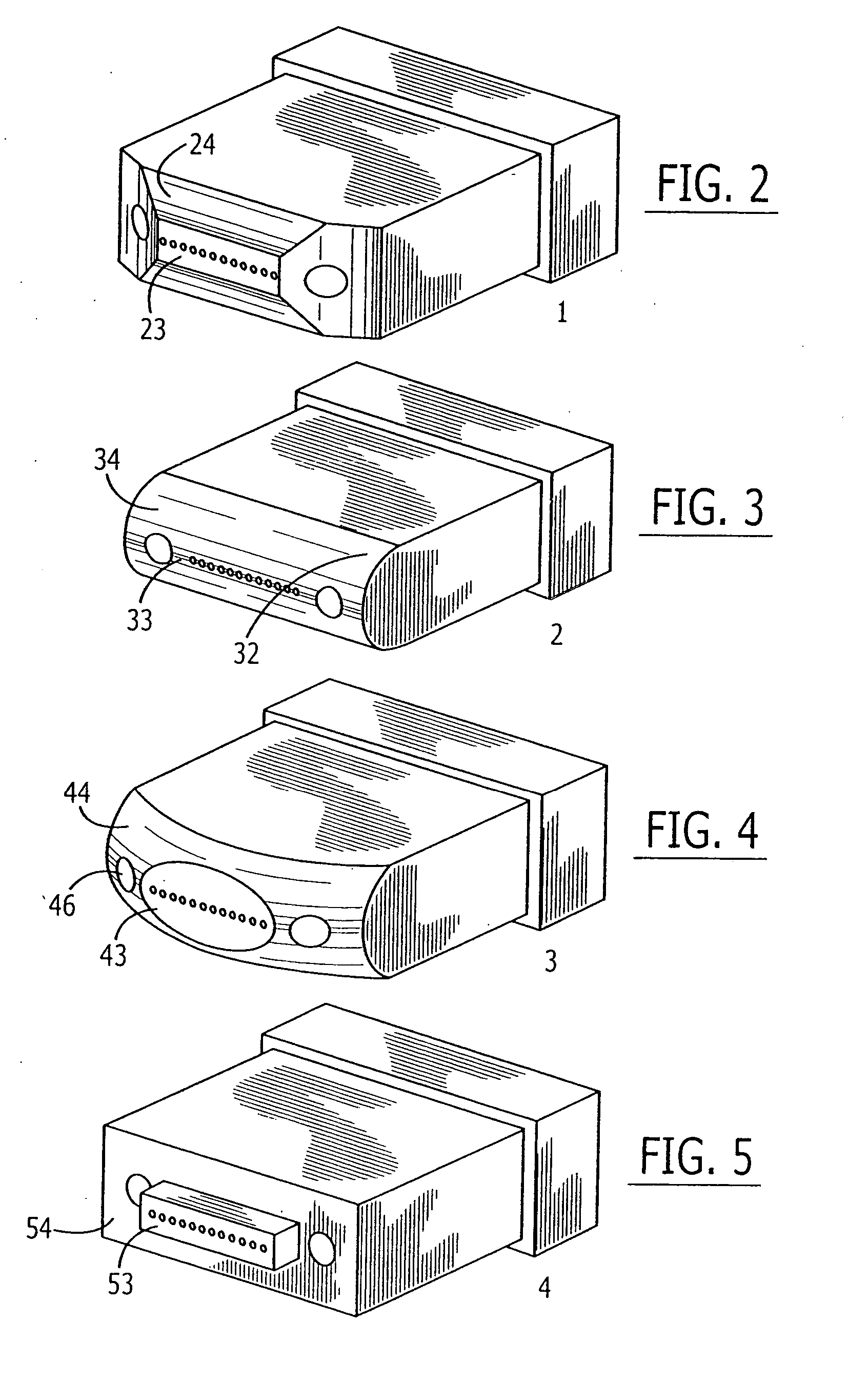
[0016] Referring to FIG. 1, a preferred embodiment of the ferrule assembly 10 of the present invention is shown. The ferrule assembly 10 comprises an array of optical fibers 15 disposed in a ferrule 11 such that the mating end 15a of each fiber is presented for mating with another connector or optical interface. The ferrule has a front and rear orientation and a front surface 12.

[0017] As used herein, the term “front surface” refers to the surface of the forward facing side (s) of the ferrule. It should be understood that a front surface may correspond to one or more distinct surfaces which may or may not be contiguous. The front surface 12 comprises a mating surface 13 and a non-mating surface 14. The mating surface 13 extends forward beyond the non-mating surface 14 and presents the mating end faces of at least one of the fibers 15.

[0018] An important feature of the present invention is that the mating surface is just a fraction of the front surface. In a preferred embodiment, t...


PUM


Abstract

A ferrule assembly comprising: (a) an array of optical fibers each having a mating end face; and (b) a ferrule with the fibers disposed therein, the ferrule having a front and rear orientation and a front surface, the front surface having at least a mating surface and a non-mating surface, the mating surface extending forward beyond the non-mating surface and presenting the mating end face of at least one of the fibers.

Description

REFERENCE TO RELATED CASE [0001] This application is a continuation of U.S. application Ser. No. 10 / 474,267, filed Oct. 6, 2003, which is a national stage application based on International Application No. PCT / US02 / 10877, filed Apr. 8, 2002, which claims priority benefit under 35 U.S.C. §119(e) to U.S. Provisional Application No. 60 / 282,201, filed Apr. 6, 2001, the disclosures of which are incorporated herein by reference.FIELD OF INVENTION [0002] The present invention relates generally to a ferrule and, more specifically, to a multifiber ferrule having an end-face geometry that facilitates improved physical contact. BACKGROUND OF THE INVENTION [0003] Optical fiber connectors are an essential part of substantially all optical fiber communication systems. For instance, such connectors are used to join segments of fiber into longer lengths, to connect fiber to active devices such as radiation sources, detectors and repeaters, and to connect fiber to passive devices such as switches an...

Claims


Application Information

Patent Timeline
Patent Type & Authority Applications(United States)
IPC IPC(8): G02B6/38
CPCG02B6/3885G02B6/3818
Inventor KEVERN, JAMES D.PATTERSON, BRIAN T.SWARTZBAUGH, JEFFGERARDUS BOLHAAR, ANTONIUS BERNARDUSHULTERMANS, ANTONIUS PETRUS CORNELIUSSCHOLTEN, MARTIJN
Owner TE CONNECTIVITY CORP
Learn More