Heat transfer to ampoule trays

a technology of ampoule trays and heat transfer, which is applied in the direction of indirect heat exchangers, lighting and heating apparatus, container discharging methods, etc., can solve the problems of difficult to meet dimensional specifications for both, large gap between the trays holding and supporting solid source precursors and the interior of the vaporizer housing, etc., to increase the amount of solid chemistries, increase the amount of consumption, and apply the correct amount.

Active Publication Date: 2019-04-25
ENTEGRIS INC
View PDF7 Cites 2 Cited by
  • Summary
  • Abstract
  • Description
  • Claims
  • Application Information

AI Technical Summary

Benefits of technology

[0005]Heat is required for an ampoule or vaporizer to sublimate the solid or liquid or crystalline precursor so it can be delivered to the semiconductor manufacturing process in a gaseous state. Heaters used are typically in the form of a heating jacket or an oven that surrounds the ampoule, hence the need to accurately and consistently apply the correct amount of heat to sublimate the precursor material within the ampoule. Further, new technology applications have increased the amount of solid chemistries being used in wafer manufacturing and have increased the amount of consumption as well as the need to efficiently v

Problems solved by technology

As vessel bodies and tray assembly combinations vary in size, depending on the application, the tolerances between them change increasing the difficulty of having a good fit between the support tray and the interior of the vessel body.
Hence, as the size of ampoules or vaporizers have increased, the inherent limitations in the manufacturing of the trays that hold the solid precursor and the vaporizer housing (the base) has dictated that the dimensional specifications for both are far more difficult to meet and had to be relaxed in order to avoid difficulty in the assembly of the ampoule.
This h

Method used


Image

  • Heat transfer to ampoule trays
  • Heat transfer to ampoule trays
  • Heat transfer to ampoule trays

Examples


Embodiment Construction

[0015]Following are more detailed descriptions of various related concepts related to, and embodiments of, methods and apparatus according to the present disclosure. It should be appreciated that various aspects of the subject matter introduced above and discussed in greater detail below may be implemented in any of numerous ways, as the subject matter is not limited to any particular manner of implementation. Examples of specific implementations and applications are provided primarily for illustrative purposes.

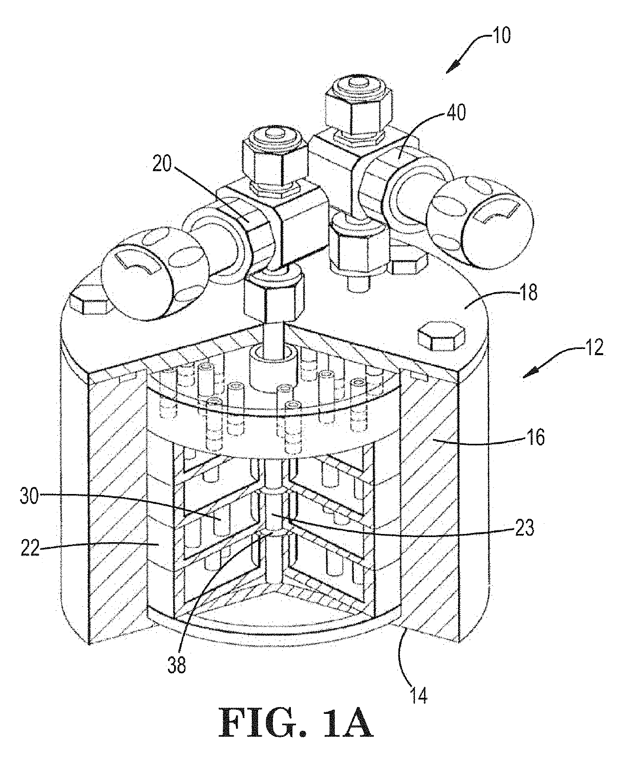
[0016]Referring to the Figures, FIG. 1A is perspective view of a prior art vaporizer 10 of a general type. The vaporizer 10 comprises a vessel body 12 fabricated of a suitable heat-conducting material. Vessel body 12 comprises a floor 14 and circumscribing sidewall 16 that together form an interior volume of the vessel. Vessel body 12 can have any shape that facilitates an even flow of carrier gas through the interior volume thereof. In one embodiment, the vessel has a cylind...


PUM

PropertyMeasurementUnit
Diameteraaaaaaaaaa
Volumeaaaaaaaaaa
Electrical conductoraaaaaaaaaa

Abstract

The invention is directed to a vaporizer or ampoule assembly with improved heat transfer between a vaporizer vessel body and at least one support tray located therein. In particular, there is provided a heat transfer enhancing member that is disposed between a vessel body and support tray. In one example of a heat transfer enhancing member or assembly there is included a heat conductive mesh or liner around totally or partially around the support tray that is wedged in between the support tray and the interior diameter or wall of the vessel body. In a related embodiment, the heat transfer enhancing member includes an expandable support tray sidewall to increase physical contact between the support tray and the vessel body interior wall.

Description

CROSS-REFERENCE TO RELATED APPLICATIONS[0001]This application claims the benefit under 35 USC 119 of U.S. Provisional Patent Application No. 62 / 574,931, filed Oct. 20, 2017, the disclosure of which is hereby incorporated herein by reference in its entirety for all purposes.FIELD OF INVENTION AND BACKGROUND[0002]The present disclosure relates generally to vaporizers useful in volatilizing solid precursors to provide precursor vapor to a precursor vapor-utilizing process system such as a vapor deposition chamber or an ion implanter and more specifically to support tray assemblies located within vaporizer vessels.[0003]In the use of solid-phase precursors to supply precursor vapor for vapor-utilizing applications, a wide variety of vaporizers have been used. Such vaporizers may comprise a vessel and cover defining an enclosed interior volume in which a solid phase precursor may be stored and subsequently subjected to volatilization conditions to effect sublimation or vaporization of th...

Claims


Application Information

Patent Timeline
IPC IPC(8): F17C7/04C23C16/448F28D21/00
CPCF17C7/04C23C16/4485F28D21/00F28D2021/0064C23C16/4481C23C14/48
Inventor HENDRIX, BRYAN C.BATTLE, SCOTT L.GREGG, JOHN N.
Owner ENTEGRIS INC
Why Eureka
Try Eureka