Ferrule assembly process

a technology of ferrules and assembly processes, applied in the field of manufacturing a ferrule assembly, can solve the problems of difficult, if not impossible, to bring the end face of the fiber housed therein into physical contact with the optical path of the mating component, and it is difficult to effect optical coupling with all of the fibers, so as to facilitate physical contact and facilitate the effect of fiber protrusion

Inactive Publication Date: 2014-06-12
VAN GEFFEN SJOERD +4
View PDF7 Cites 2 Cited by
  • Summary
  • Abstract
  • Description
  • Claims
  • Application Information

AI Technical Summary

Benefits of technology

[0010]The present invention provides a ferrule assembly in which precise fiber protrusion is achieved without polishing. Specifically, the invention involves using a tool that has a register surface and one or more alignment members that cooperate with one or more alignment members of a ferrule to align the register surface of the tool with the ferrule end face, and thereby provide a register surface against which each fiber can abut to ensure its proper protrusion. Proper fiber protrusion facilitates physical contact among the fibers as described above. It should be understood, however, that the invention is not limited to physical contact applications and may be practiced whenever precise positioning of the fiber end face is required (such as, for example, when optically coupling a fiber across a gap (air or gel-filled) to a lens, active opto electrical device, passive device, or a waveguide). Thus, the invention exploits alignment members that are commonly found in standard ferrules to establish fiber protrusion.

Problems solved by technology

An unpolished ferrule has a geometry and anomalies on its end face which make it difficult, if not impossible, to bring the end face of fiber housed therein into physical contact with the optical path of the mating component.
In addition, when multiple fibers are affixed to an unpolished ferrule, the position of the fiber end faces tend to vary along the mating axis, thereby making it difficult to effect optical coupling with all of the fibers.
Polishing therefore tends to be costly and prone to reworking and waste, thereby lowering yields.
The problems associated with polishing the ferrule are exasperated in multi-fiber ferrules which are more complicated to polish.
Although this approach offers significant advantages, applicants recognize that coplanarity among the fibers tends to become problematic as the number of fibers in the ferrule increases.
That is, cleaving fibers and positioning them in the ferrule such that all the fiber end faces are essentially in the same plane is very difficult when the fibers are not polished in situ in the ferrule.
This difficultly increases necessarily as the number of fibers increases.

Method used


Image

  • Ferrule assembly process
  • Ferrule assembly process
  • Ferrule assembly process

Examples


Embodiment Construction

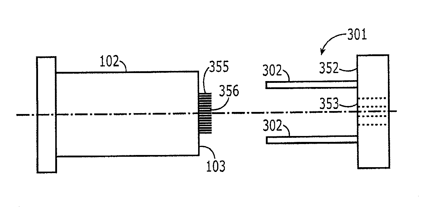
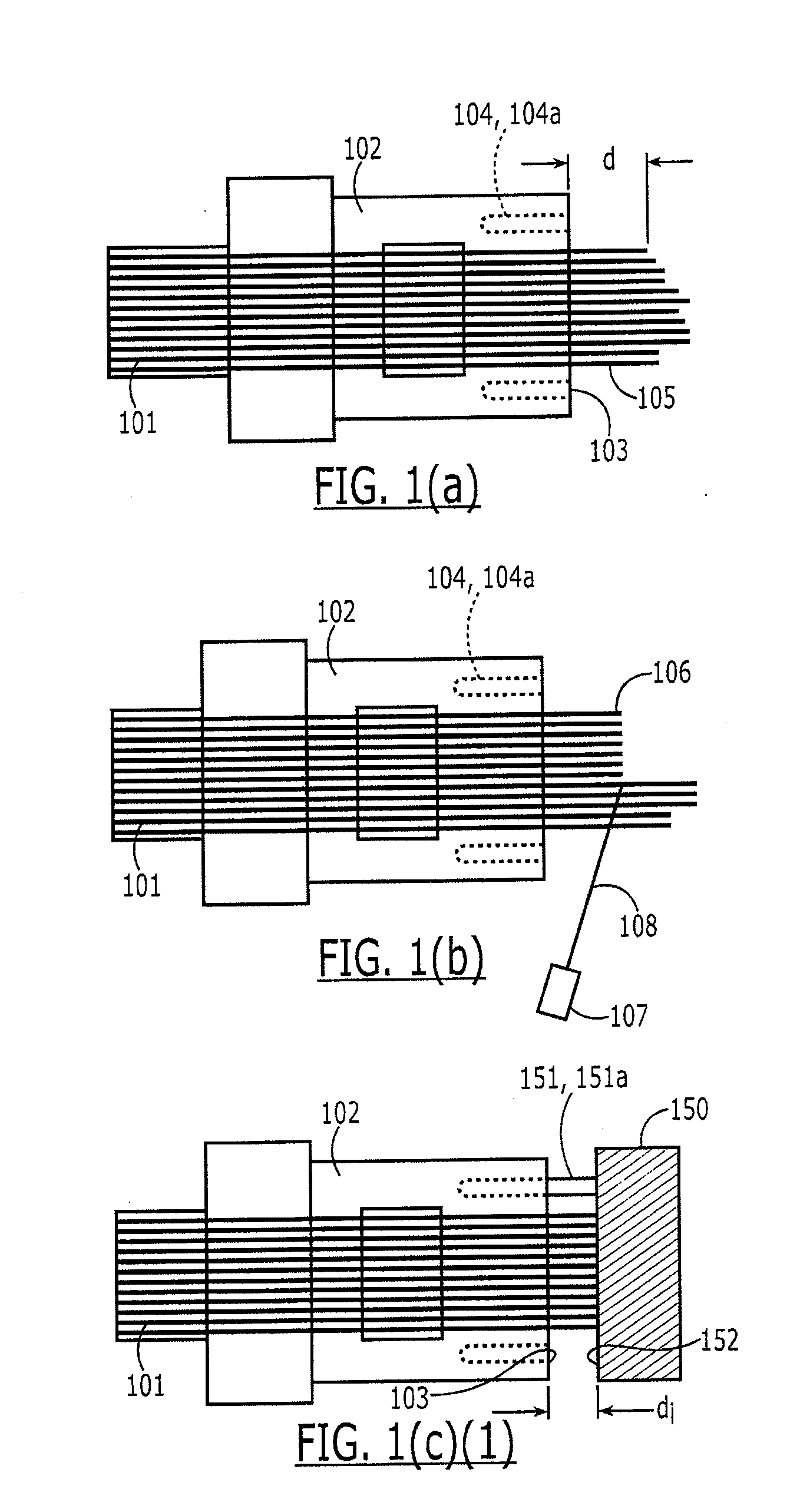
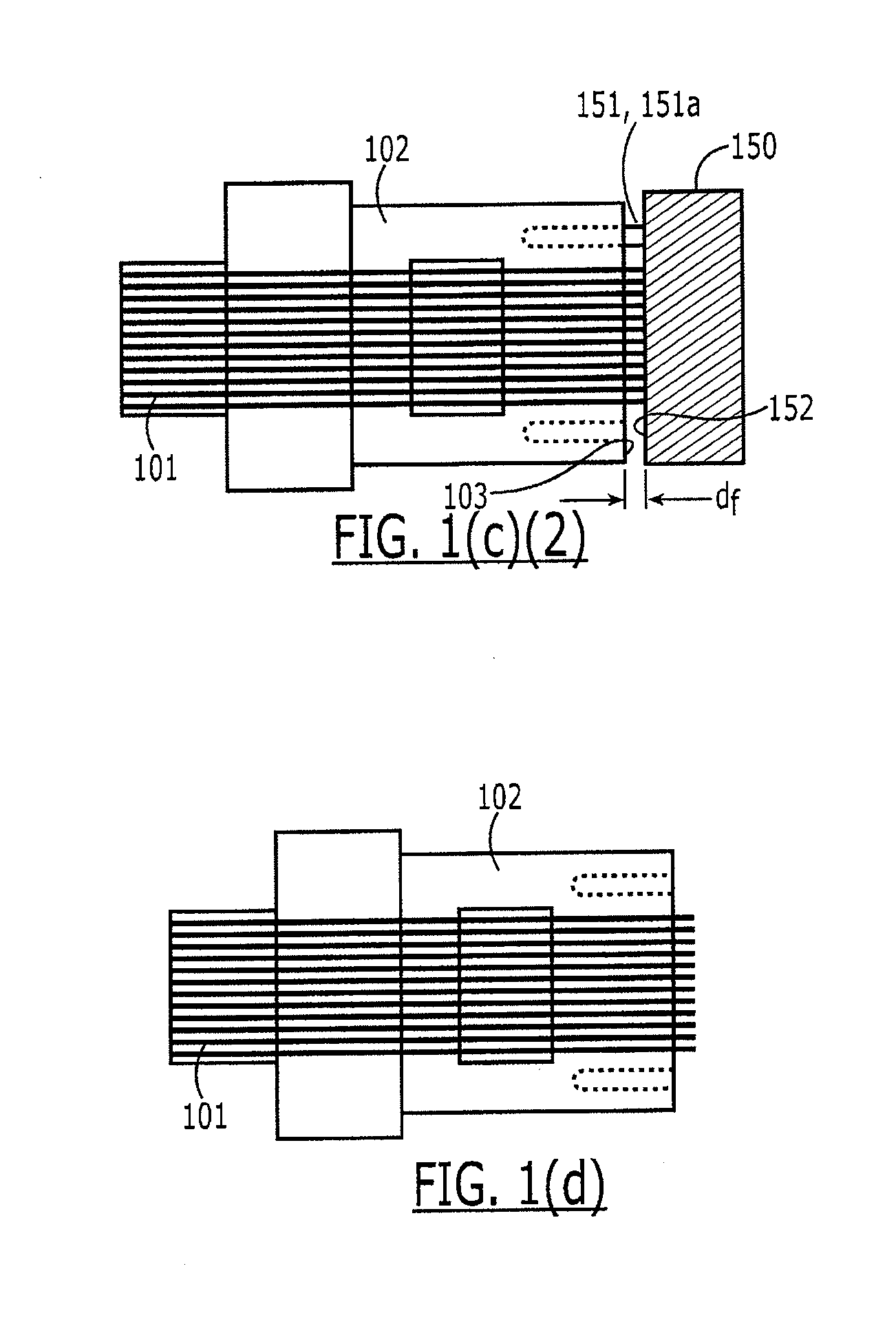
[0018]Referring to FIGS. 1(a)-(d), a process for preparing terminated fibers according to one embodiment of the present invention is shown. (Although this description considers a multifiber ferrule in detail, it should be understood that the invention may be practiced on single fiber ferrules as well.) As shown schematically in FIG. 1(a), multiple fibers 101 are positioned in a ferrule 102 having a ferrule end face 103 and at least one first alignment member 104 such that a portion 105 of each of the fibers 101 extends beyond the ferrule end face 103. The portion of the fibers 101 extending from the ferrule end face 103 is then cleaved to form cleaved fiber ends 106 as shown in FIG. 1(b). Next, as shown in FIG. 1(c), a second alignment member 151 of a tool 150 is interengaged with the first alignment member 104 such that a register surface 152 of the tool 150 is aligned with the ferrule 102. The cleaved fiber end faces 106 are then registered against the register surface 152, thereb...


PUM

PropertyMeasurementUnit
angleaaaaaaaaaa
peak poweraaaaaaaaaa
pulse lengthaaaaaaaaaa

Abstract

A tool for aligning fibers in a ferrule, the tool comprising a body portion having a register surface; and at least one alignment member at a certain angle from the register surface, the alignment member configured to cooperate with a corresponding alignment member of a ferrule, wherein the register surface is non-planar.

Description

CROSS REFERENCE TO RELATED APPLICATIONS[0001]This application is a divisional of U.S. application Ser. No. 12 / 872,315, filed Aug. 31, 2010, all of which is hereby incorporated by reference.FIELD OF THE INVENTION[0002]The present invention relates generally to a process of manufacturing a ferrule assembly, more specifically, to controlling to fiber protrusion of a ferrule assembly.BACKGROUND OF INVENTION[0003]Optical fiber connectors are an essential part of substantially all optical fiber communication systems. For instance, optical connectors are used to join segments of fiber into longer lengths, to connect fiber to active devices such as radiation sources, detectors and repeaters, and to connect fiber to passive devices such as switches and attenuators. The principal function of an optical fiber connector is to hold a fiber end such that the core of the fiber is axially aligned with the optical path of the component to which the connector is mated (e.g., another fiber, a planar w...

Claims


Application Information

Patent Timeline
Patent Type & Authority Applications(United States)
IPC IPC(8): G02B6/38
CPCG02B6/25G02B6/3818G02B6/3833G02B6/3885G02B6/3898Y10T29/49895Y10T29/53913G02B6/3834
Inventor VAN GEFFEN, SJOERDHULTERMANS, ANTONIUS P.C.M.KADAR-KALLEN, MICHAEL AARONBUIJS, MARCELLUS P.J.SCHNEIDER, PAUL
Owner VAN GEFFEN SJOERD
Why Eureka
Try Eureka