Thickness gradient protective overcoat layers by filtered cathodic arc deposition

a protective layer and thickness gradient technology, applied in the field of thickness gradient protective overcoat layers by filtered cathodic arc deposition, can solve the problems of limiting the recording density, degrading performance parameters such as, for example, signal-to-medium noise ratio (smnr), and unrecoverable data loss, and achieve the effect of improving magnetic or magneto-optical (mo) recording media

Inactive Publication Date: 2005-11-10
SEAGATE TECH LLC
View PDF17 Cites 17 Cited by
  • Summary
  • Abstract
  • Description
  • Claims
  • Application Information

AI Technical Summary

Benefits of technology

This patent describes an improvement in methods for depositing layers of materials onto surfaces through a process called filtered cathodic arc deposition (FCAD). These improvements involve creating layers with different thicknesses within one area, resulting in a thicker region near the edge where two areas meet. This technique can also be used when applying a protective overcoat to magnetic or optical storage devices. Additionally, this patent provides better results in forming these layers with specific patterns that enhance performance.

Problems solved by technology

The technical problem addressed in this patent is how to form protective overcoat layers on magnetic and mojo-optical disks with multiple zones of varying thicknesses without causing difficulty in achieving the required thickness variations using traditional methods like sputter and ion beam deposition. This invention provides new ways and methods for rapidly and reliably forming these protective overcoats with abrupt transition zones between thinner and thicker parts, compatible with existing production technologies.

Method used


Image

  • Thickness gradient protective overcoat layers by filtered cathodic arc deposition
  • Thickness gradient protective overcoat layers by filtered cathodic arc deposition
  • Thickness gradient protective overcoat layers by filtered cathodic arc deposition

Examples


example

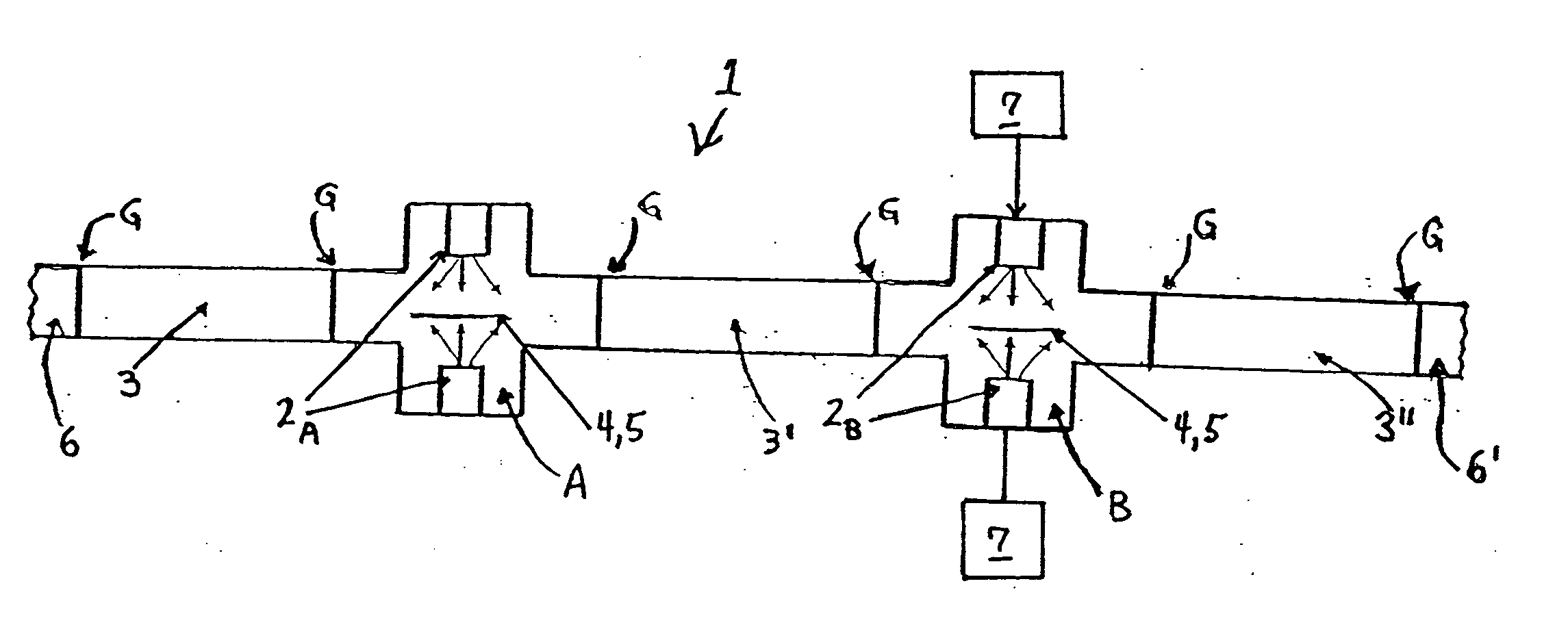
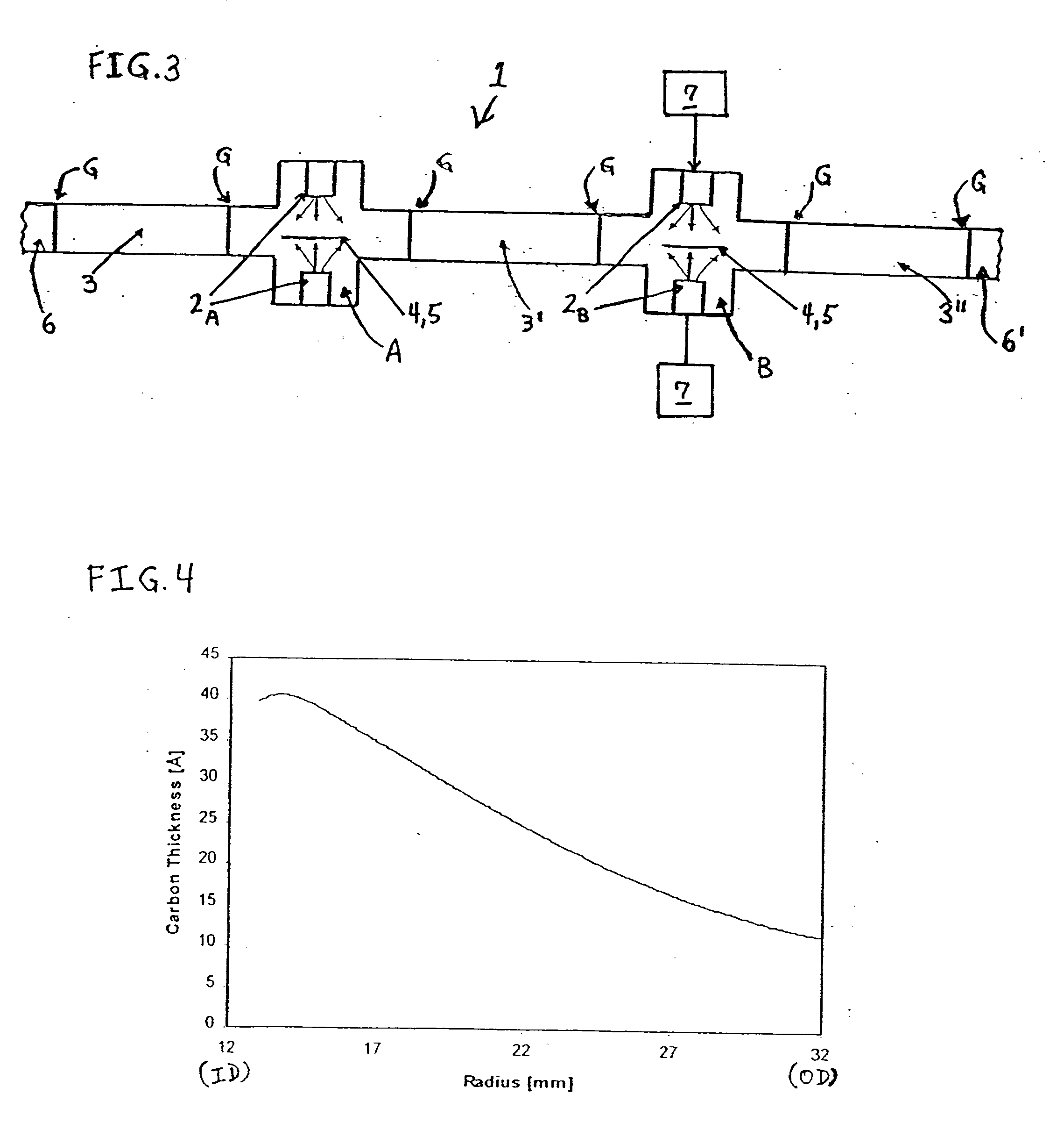
[0076] A FCAD plasma beam containing carbon particles was scanned around the ID of an annular disk-shaped recording medium with a 12 mm radius at the ID and a 32 mm radius at the OD to form a FCAD carbon layer with a thickness gradient between the ID and the OD. FIG. 4 is a graph illustrating an estimated radial thickness profile of the carbon layer formed by the scanned FCAD method of the present invention, which radial thickness profile was obtained by assuming a linear relationship between the reflectivity of the FCAD carbon layer and its thickness, and by estimating the thickness at the ID and OD to be ˜40 Å and ˜10 Å, respectively. While this medium was fabricated with a relatively large width (i.e., ˜1 cm diameter) FCAD plasma beam that had been previously been optimized for providing carbon-containing protective overcoat layers with full surface thickness uniformity and deposition rate, the beam can be focused to a smaller diameter in order to provide a sharper thickness grad...


PUM

PropertyMeasurementUnit
Thicknessaaaaaaaaaa
Diameteraaaaaaaaaa
Sizeaaaaaaaaaa

Abstract

A method of depositing a layer of a coating material (e.g., DLC protective overcoats of magnetic and magneto-optical recording media) on a surface of a substrate/workpiece, the layer including relatively thin and relatively thick regions defining a thickness gradient at a boundary therebetween, comprising steps of: (a) providing a filtered cathodic arc deposition (FCAD) process/treatment chamber comprising a FCAD source including means for providing a focused plasma beam containing ions of a coating material and means for scanning the plasma beam over a substrate/workpiece surface; (b) providing the process/treatment chamber with a substrate/workpiece including a surface for deposition thereon; and (c) forming on the surface a layer of coating material including the relatively thin and relatively thick regions defining the thickness gradient at the boundary therebetween by scanning the plasma beam over at least a portion of the surface.

Description


Claims


Application Information

Patent Timeline
Owner SEAGATE TECH LLC
Why Eureka
Try Eureka