
Universal electrical plug and socket

a multi-prong, plug-in technology, applied in the direction of coupling device connection, coupling protective earth/shielding arrangement, electric discharge lamps, etc., can solve the problems of inability to adapt the power cord, the extension cord receptacle cannot facilitate a voltage change, and the electrical device with which the plug is associated is ungrounded, etc., to achieve convenient production, simple, reliable, and inexpensive

Inactive Publication Date: 2005-11-10
ALLISON BRIAN
View PDF7 Cites 38 Cited by
  • Summary
  • Abstract
  • Description
  • Claims
  • Application Information

AI Technical Summary

Benefits of technology

[0027] The present invention provides an improved variable connection device that is simple, inexpensive, reliable, and easy to produce. The present invention is simple, in that it utilizes a universal multi-prong plug and socket that can be configured with different conductive prongs depending on the available electrical service. The present invention is inexpensive, in that most electrical devices require a power plug and cord assembly when connecting to electrical service, so the present invention adds nothing to the manufacturing or production cost. The present invention is reliable, in that the different embodiments are hardwired and encased in nonmetallic insulating material. The embodiments are constructed and arranged using proven methods of power cord manufacturing, making the present invention as reliable as any other commercially available power cord. The present invention is easy to produce due to the simple and elegant design. Any power cord manufacturer can use commercially standard production techniques to build the present invention for any embodiment utilizing the various electrical services available.

Problems solved by technology

When retracted for use with a 2-wire outlet, however, this leaves the electrical device with which the plug is associated ungrounded.
These adaptations to different wall outlet or extension cord receptacles do not facilitate a voltage change, only the mechanical connection between the receptacle and the power plug.
This adaptation by power cord could not be accomplished without the unique four prong plug socket and plug.
However, the Henrich '128 patent does require two transformers causing parasitic losses and additional expense.
The '545 patent also employs a selector switch that would also be prone to failure during high “in rush” currents during start up of certain electrical devices.
However, the Lee '760 patent still relies on a selector switch and other electrical components to accomplish the power voltage conditioning increasing expense and failure rates.
The '760 patent also is susceptible to the “in rush” current problem during start up of certain electrical devices that would increase the failure rate of the switch and supporting electrical components.
However, the DiGirolamo '636 patent relies on an external transformer adding expense and other electrical components increasing the failure rate of the overall system.
While the above-described devices fulfill their respective, particular objectives and requirements, the aforementioned patents do not describe a simple inexpensive device that when employed, does not increase the over all failure rate of the appliance or electrical device while in operation.
Also, many of the above-described devices have a selectable switch that will fail due to high “in rush” currents during start up of some electrical devices.

Method used


Image

  • Universal electrical plug and socket
  • Universal electrical plug and socket
  • Universal electrical plug and socket

Examples


Embodiment Construction

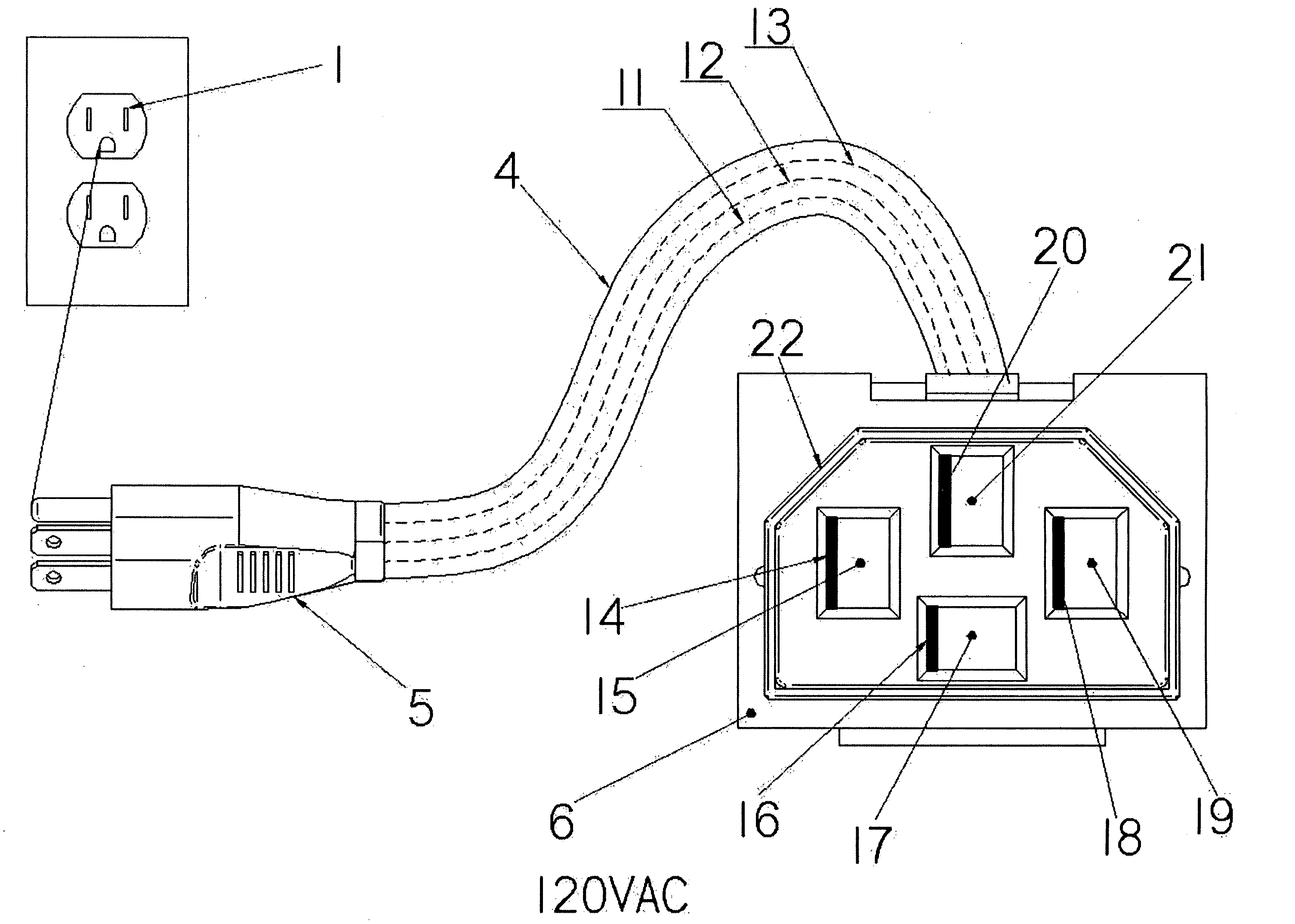
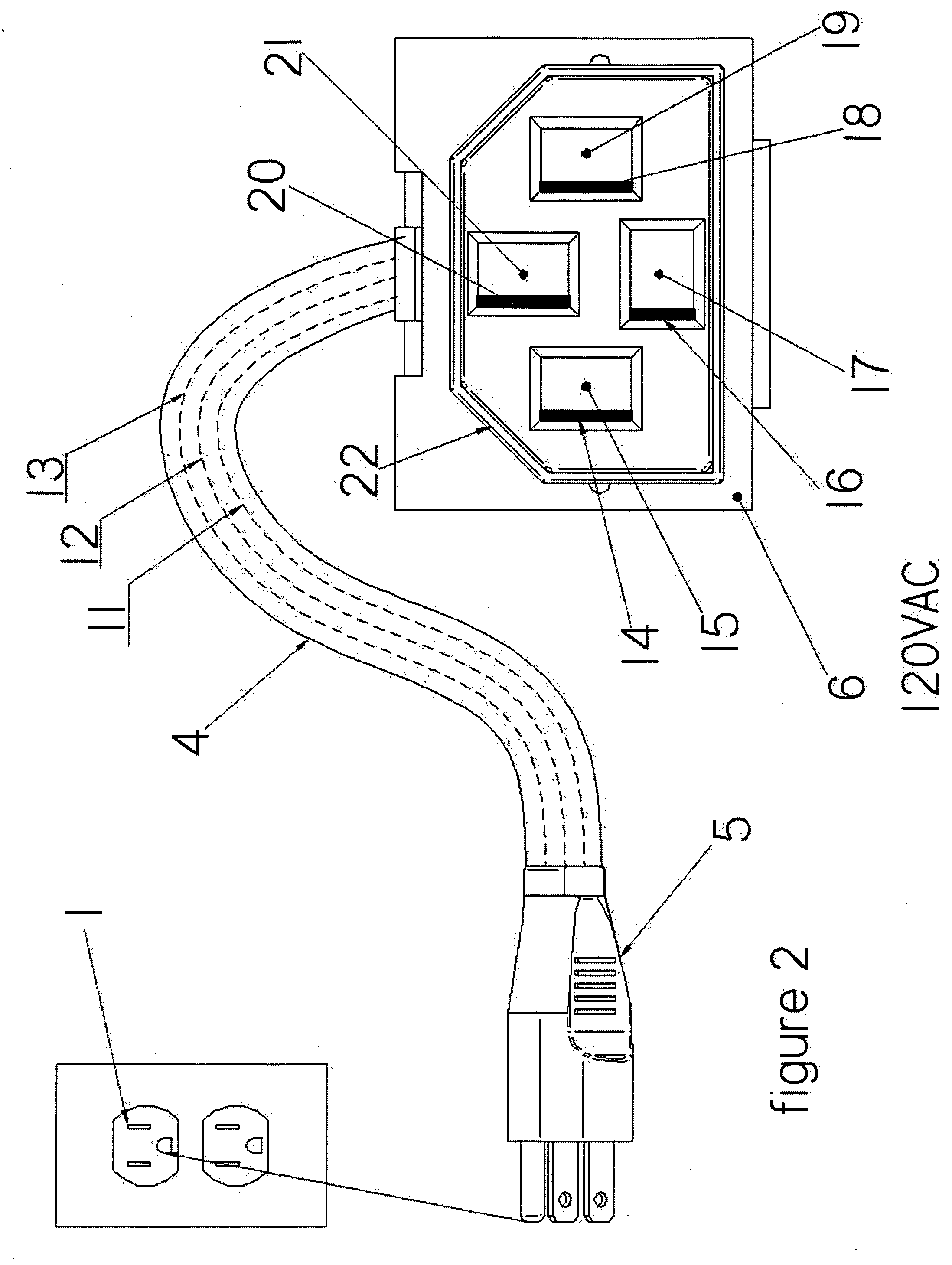
[0035] Referring now to the drawings, and particularly to FIGS. 1-5, a preferred embodiment of the present invention is shown, illustrating the universal electrical plug and socket configured for use in either a 120VAC or 240VAC service voltage.

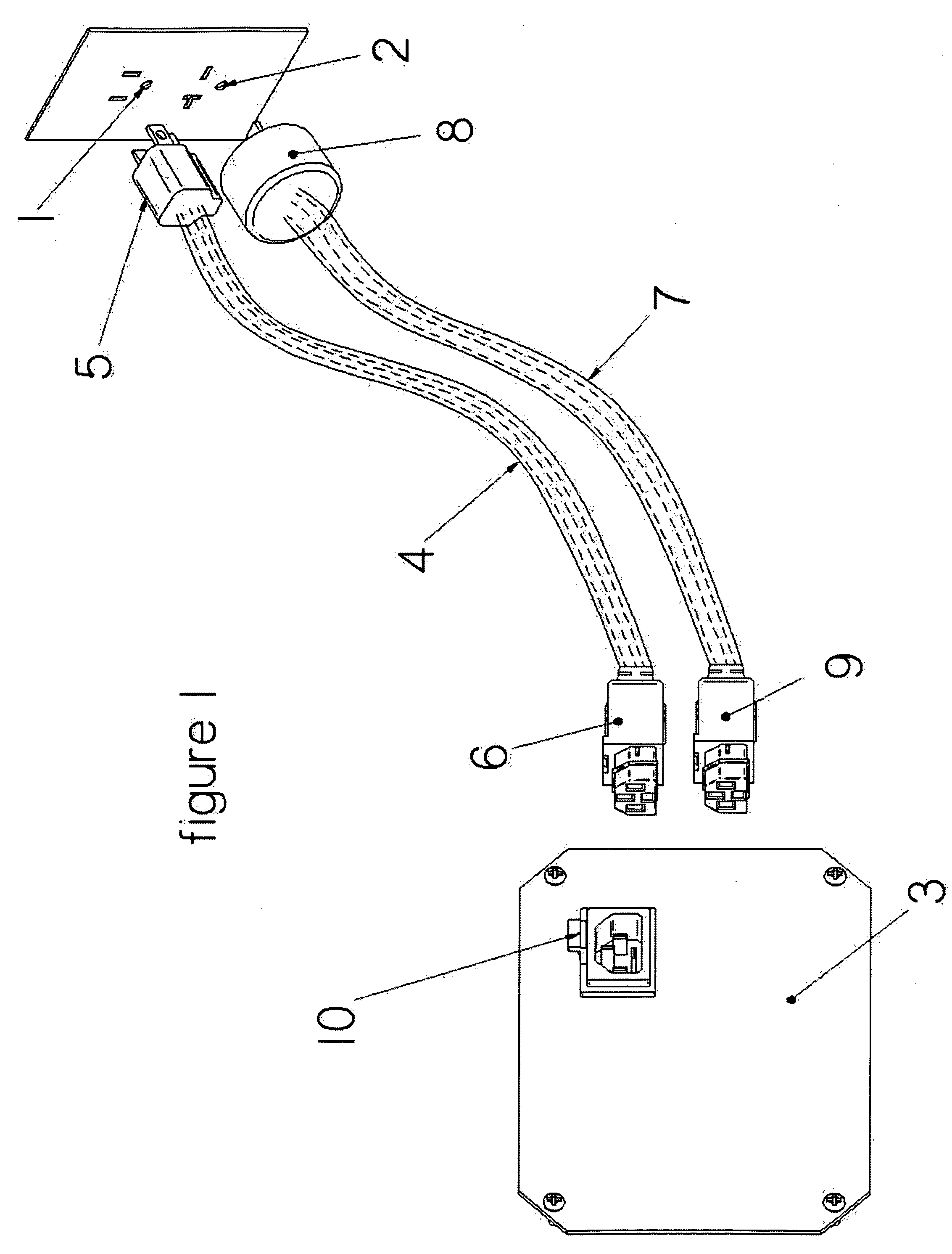
Description FIG. 1:

[0036]FIG. 1 illustrates one embodiment of the present invention facilitating electrical connection of an electrical device 5, to two different potential service voltages and wall socket configurations, one being 120VAC 1 and the other being 240VAC 2. The 120VAC power cord assembly 4 has on one end a standard 120VAC wall socket plug 3, and on the other end the universal plug 6. The 240VAC power cord assembly 7 has on one end a standard 240VAC wall socket plug 8, and on the other end the universal plug 9. The universal plug 6 and the universal plug 9 are identical, both fittingly insertable into universal socket 10.

[0037] Being of simple design and elegant utility, the end user selects the power cord to match the desired...


PUM


Abstract

A socket and plug assembly, comprising a socket member including a housing that confines a plug receiver space and defining an axial direction, said socket member further including a socket face plate internal to the housing and perpendicular to the axial direction defining the depth of the plug receiver space, further including at least four conductive prongs mounted through and projecting outwardly from said socket face into said plug receiver space, said conductive prongs also extending oppositely in the axial direction through the non-conductive housing, said conductive prong ends extending out through said non-conducting housing permitting electrical connection to an electrical device; and a plug member fittingly insertable into said receiver space of said mated socket member, including a non-conducting plug case having a plug face side and a power cord side, further including at least four prong cavities open on the plug face side being in spatial communication with the number, fit, and configuration of said conductive prongs protruding from said socket face plate, including one or more internal conductive terminals captively connected within said prong cavities, said internal conductive terminals being conductively exposed inside the prong cavities, constructed and arranged to induce electrical connection with said conductive prongs when said conductive prongs are received into said prong cavities, said internal conductive terminals projecting outwardly from the non-conducting plug case along the axial direction on the power cord side permitting electrical connection between the internal conductive terminals and a power cord.

Description

CROSS REFERENCES TO RELATED APPLICATIONS [0001] Provisional Patent Application filed on May 10, 2004, application No. 60 / 569,160.STATEMENT REGARDING FEDERALLY SPONSORED RESEARCH OR DEVELOPMENT [0002] This invention is not the product of any Federally Sponsored Research or Development. REFERENCE TO MICROFICHE APPENDIX [0003] Not Applicable TECHNICAL FIELD [0004] The invention relates to a multi-prong Electrical Plug and Socket, for use in electrically interconnecting appliances, lighting fixtures, and electrical tools, to various voltages and wall socket configurations including 120VAC and 240VAC. Connecting electrical devices to electrical service is well known in the art. Most well known methods involve a power cord plugging into an outlet, the other end of the power cord hardwired to the device. If the outlet voltage is different than what the electrical device is hardwired for, a voltage adapter or power converter must be employed between the electrical device and power service t...

Claims


Application Information

Patent Timeline
Patent Type & Authority Applications(United States)
IPC IPC(8): H01R11/00H01R29/00H01R31/06H01R33/94H05B41/14
CPCH01R13/652H01R24/22H01R2103/00H01R29/00H01R31/06H01R24/30
Inventor ALLISON, BRIAN
Owner ALLISON BRIAN
Learn More