Method and apparatus for high throughput multiple radio sectorized wireless cell

a wireless cell, multi-radio sector technology, applied in the field of wireless communication, can solve the problems of limited current generation of wireless access points and devices, and achieve the effect of minimizing interference with foreign wireless systems and increasing throughpu

Inactive Publication Date: 2005-11-10
ROTANI
View PDF32 Cites 32 Cited by
  • Summary
  • Abstract
  • Description
  • Claims
  • Application Information

AI Technical Summary

Benefits of technology

[0005] The invention overcomes the limitations and problems of the prior art by providing an improved wireless cell that wirelessly communicates with other apparatus. In one embodiment, the enhanced antenna system includes at least one of sectorized coverage, attenuation, overlapping or non-overlapping antenna physical sector arrangements, and minimally interfering radio channels to enable multiple antennas and multiple radios to substantially simultaneously operate in a single wireless cell and to provide increased throughput, while minimizing the interference with foreign wireless systems.

Problems solved by technology

However, the current generation of wireless access points and devices are limited in that they use omni-directional antennas assigned to a single channel.

Method used


Image

  • Method and apparatus for high throughput multiple radio sectorized wireless cell
  • Method and apparatus for high throughput multiple radio sectorized wireless cell
  • Method and apparatus for high throughput multiple radio sectorized wireless cell

Examples


first embodiment

[0107] Other potential variations on the enhanced antenna system first embodiment may include using the antenna that receives the strongest receive signal exclusively for reception and the antenna that transmits the strongest transmit signal exclusively for transmission without requiring the transmit and receive antennas to be the same. The antennas may also be arranged to be non-overlapping, but also non-adjacent.

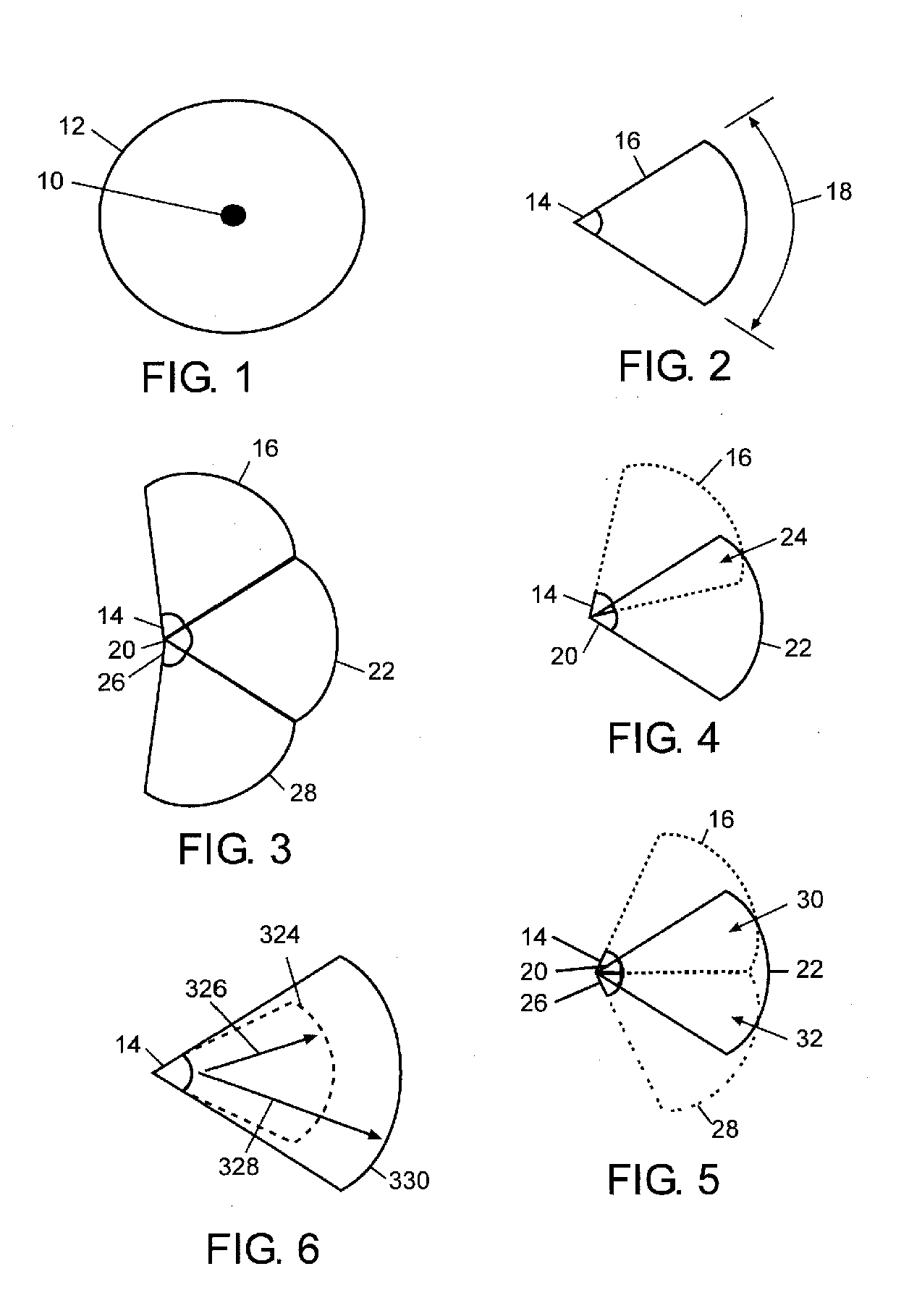
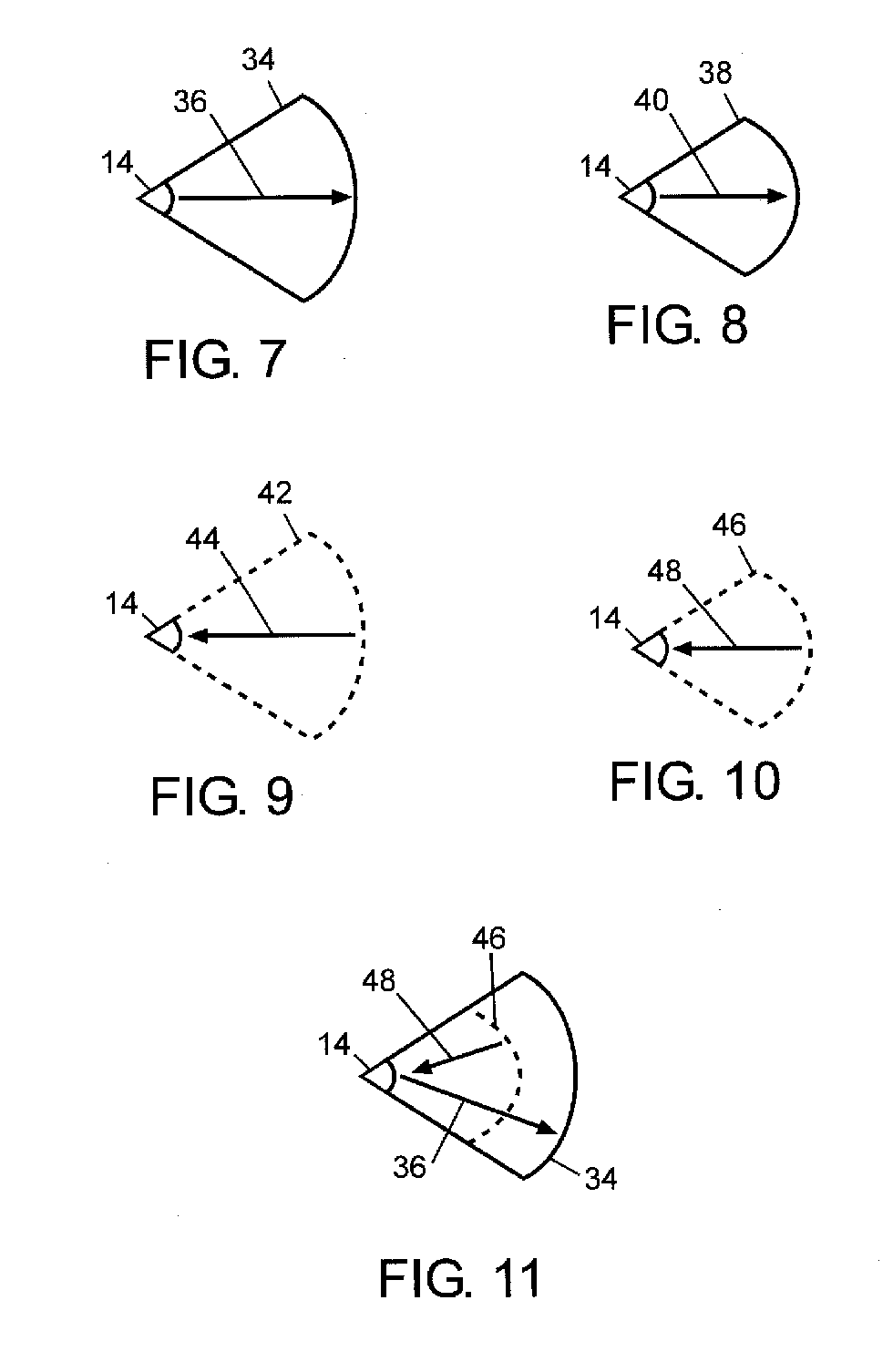
[0108] A second embodiment of an enhanced antenna system uses multiple directional antennas arranged such that the antenna physical sectors overlap. Unlike the first embodiment of an enhanced antenna system, multiple antennas in the second embodiment may be simultaneously active, which may increase the desirability of the second embodiment for a wireless cell. Exemplary patterns for overlapping physical sectors are shown in FIG. 4, FIG. 5, FIG. 14, FIG. 17, and FIG. 20. The exemplary antennas and hardware shown in FIG. 22, FIG. 25, FIG. 28, or FIG. 29 may be adapted to pro...

second embodiment

[0112] The hardware shown in FIG. 29 does not represent a current off-the-shelf-radio because the radio through an RF switch attaches to more than two antennas. However, the antenna physical sectors may be arranged to provide the overlapping wireless cell coverage pattern of FIG. 34, thereby meeting the enhanced antenna system second embodiment feature of overlapping sectors.

[0113] Another possible antenna physical sector arrangement includes physical sectors which overlap by about 100% thereby forming virtual sectors substantially equal in size to a physical sector. An example of such a scheme may exist where at least two antenna physical sectors are assigned to position 62 in FIG. 13, at least two additional antenna physical sectors are assigned to position 64, and at least an additional two antennas to position 66. The physical sectors of the antennas in each position 62, 64, or 66 may completely overlap and form virtual sectors the size of the individual antenna physical sector....

third embodiment

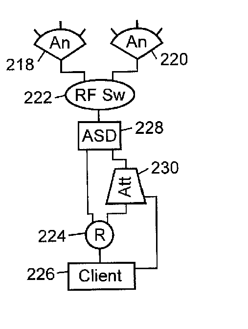
[0114] an enhanced antenna system is similar to the second embodiment in that it uses multiple directional antennas arranged such that the antenna physical sectors overlap; however, the third embodiment may be different in that, for example, an attenuator is placed between each antenna and its corresponding RF switch as shown in FIG. 24 and FIG. 27. The third embodiment has the advantage of virtual sectors covered by multiple antennas, along with the ability to attenuate the effects of unwanted receive signals with the attenuators. The level of attenuation may be changed between transmission and reception; thereby, allowing the wireless cell to attenuate unwanted receive signals while still transmitting at substantially full strength. The attenuator and methods of attenuation are described in more detail below. The arrangement of the antenna physical sectors of the enhanced antenna system third embodiment may be similar to the overlapping arrangements described in the second embodim...


PUM


Abstract

Methods and apparatus for high throughput wireless cells, capable of functioning as access points, are described. The wireless cells may be equipped with multiple radios to increase the amount of throughput available through a single wireless cell. Multiple antennas attached to the radios through RF switches may enable the wireless cell to service multiple clients simultaneously. The physical sectors of the antennas may overlapped to form virtual sectors that provide greater flexibility in client load management and in simultaneously servicing multiple clients. Attenuators may reduce interference from foreign wireless cells or clients. Systems and methods for assigning minimally interfering channels to either physical sectors or to radios to reduce interference between adjacent sectors and overlapping sectors are also disclosed. An antenna horn may also allow any antenna to be used as a directional antenna and may enable the antenna's angle of coverage to be adjusted. The use of multiple antennas on a client to reduce interferences is also described.

Description

CROSS-REFERENCE TO RELATED APPLICATIONS [0001] This application is a divisional of and claims priority to, and the benefit of, U.S. patent application Ser. No. 10 / 869,201, filed Jun. 15, 2004, which is hereby incorporated by reference in its entirety. This application also claims priority to, and the benefit of, U.S. provisional application Ser. No. 60 / 484,800 filed on Jul. 3, 2003, which is also hereby incorporated by reference in its entirety, and to U.S. provisional application Ser. No. 60 / 493,663 filed on Aug. 8, 2003, which is also hereby incorporated by reference in its entirety.NOTICE OF MATERIAL SUBJECT TO COPYRIGHT PROTECTION [0002] A portion of the material in this patent document is subject to copyright protection under the copyright laws of the United States and of other countries. The owner of the copyright rights has no objection to the facsimile reproduction by anyone of the patent document or the patent disclosure, as it appears in the United States Patent and Tradem...

Claims


Application Information

Patent Timeline
Patent Type & Authority Applications(United States)
IPC IPC(8): H01Q3/26H04B7/02H04B7/04H04L12/28H04L12/56H04W16/00H04W16/02H04W16/12H04W16/14H04W16/24H04W40/02H04W74/06H04W88/06
CPCH01Q3/2605H04B17/382H04B7/0408H04B7/0491H04B7/0495H04W16/00H04W16/02H04W16/12H04W16/14H04W16/24H04W28/04H04W28/16H04W40/02H04W74/06H04W88/06H04B7/022Y02D30/70
Inventor LASTINGER, ROCSPENIK, JOHNWOODBURY, BRIAN C.
Owner ROTANI
Why Eureka
Try Eureka